
User's Manual

T-0000-0004-V2.1: Using Mozart II
T-0000-0004-V2.1: Using Mozart II Page: 3 / 24
All the internal peripherals are supported by the software distribution, as well as some external
peripherals. The module has its own reset circuitry, which generates an externally available signal for
resetting external devices. This reset line will be asserted at power on, when a power supply failure is
detected, or when the software reboots the module (this can happen after firmware upgrade for
instance). If the reset line is not used by an external device, care must be taken to reset the device at
least under power on and power failure conditions by additional means.
4.2 EXTERNAL CONTROLS & INPUTS
The module features a number of pins that allow sensing data from the outside world as well as
control information. Several digital I/O pins are available. All digital inputs are interrupt-capable in
order to trigger predetermined software behaviors upon given external conditions. Digital outputs are
3.3v CMOS outputs; their maximum output current is 10 mA.
4.3 EXTERNAL BUSES
4.3.1 I2C
The module acts as an I2C compatible master controller. The default bus speed is 100KHz. The bus
level is 3.3v; the module already has 4k7 pull-up resistors on both SCL and SDA lines. The external
lines, if used without repeater, should be kept as short as possible.
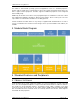
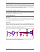
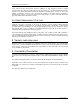
4.3.2 USB
Signals for an USB host interface are available. The
interface is fully compliant with USB 2.0 fullspeed
standard. The powering of external USB devices is left to the integrator and must comply with USB
constraints (coil decoupling of powering and appropriate impedance matching and adaptation of lines).
Most often, the host interface will be used for USB keys or mass storage devices. Should more USB
ports be needed, an external hub can be added on the module port.
DGND
J2
Conn USB ty pe A horiz
USB_5V
1
HOST_D-
2
HOST_D+
3
DGND
4
FGND
6
FGND
5
L1 120R 100MHz
USB
L2
120R 100MHz
C3
47p 50V
C4
47p 50V
HD M
HD P
DGNDDGNDDGND
+
C2
47u 16V
DGN DDGND DGNDDGND
VCC5V
C1
100n 16V
HDM
R2
DNP
ESD5 ESD6
ESD7 ESD8
USB_GND
R1
4k7
HDP
USB_5V
DGNDDGND
U2 LM3525M-L
IN
7
FLG
2
EN
1
GND
3
NC1
4
NC2
5
OUT1
6
OUT2
8
DGN D
USB Mass Storage Support is part of the standard software delivery. Note that USB device or OTG
can be supported but is not part of the standard implementation