
User's Manual


Data Sheet: CR Series
JukeBlox Networked Media Modules
dat_CR860_CR870_2_14_datasheet.doc CONFIDENTIAL Version 2.14 – June 10
th
2010 - Page 11 of 15
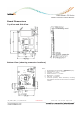
The pinout and signal names are shown on the next page. The following table provides an overview
for the most important control and interface signals.
Key Connections
Signal(s) Connector ID Pin
Number(s)
Description
J2 3, 4, 5, 6 Input voltage; +3.3V
J2 9, 10, 11, 12 Input voltage; +1.2V
J3 4, 6 Input voltage; +1.8V
J3 10 Input voltage; +3.3V
VIN
J3 12 Input voltage; +1.5V
SPI_DOUT
SPI_DIN
SPI_CLK
SPI_NCS0, 1
J2
J2
J2
J2
25
27
29
30, 32
SPI bus from DM870’s SPI controller.
SPI_REQ J2 64 PDOUT1 signal used as SPI_REQ for eDMP applications
RXD1, TXD1 J2 35, 37 3.3V logic level UART I/Os for the debug UART.
Provide external RS-232 transceiver to connect to a PC’s
COM port.
NRESET_MOD J2 34 Low-active input to reset the module;
internal 10K pull-up
NPD_RF J2 119 Low-active input to shut down the power for the
802.11 Rf part;
internal 10K pull-up
AOUTLP/AOUTLN J2 63, 65
AOUTRP/AOUTRN J2 60, 58
Differential stereo output from PWM-DAC.
BIST activate J2 48 Low-active input to invoke the production BIST;
DM870-internal pull-up
Factory Reset J2 68 High-active input to reset the configuration;
DM870-internal pull-down
IR input J2 70 Infrared sensor input. This is a Schmitt-Trigger input
and can handle interrupt inputs with slow slopes.
ETH_NRESET J2 72 Low-active reset for the on-board Ethernet phy. This
output is driven by the DM870 and is not suited for
other purpose.
SDA, SCL J2 73, 75 I2C bus created by GPIO-14 and GPIO-13.
No internal pull-ups; if I2C is to be used, please add the
proper external pull-up resistors.
ETH_LED_ACT
ETH_LED_SPEED
J2
J2
100
102
3.3V push-pull outputs (max. ±12mA) to drive the
Ethernet LEDs.
A low-level indicates 100Mbps mode and activity
respectively.