COMPANY CONFIDENTIAL 4F, 90, Chien 1 Road, Chungho, New Taipei City 235, Taiwan, R.O.C. TEL: +886-2-2222-6181 Fax: +886-2-2222-3882 光寶科技股份有限公司 台北縣中和市建一路 90 號 4F 電話: 02-2222-6181 傳真: 02-2222-3882 客 戶 名 稱: Customer Name: D&M 承 Holdings Inc. 認 書 (Specification Sheet) 品 名 (Part Name) 承認書版本(Approval Sheet Rev.) 客戶料號 (Customer Part No.) 光寶料號 (Liteon Part No.
COMPANY CONFIDENTIAL Index Index ......................................................................................................................................................... 2 Part1. Module Spec Sheet .................................................................................................................... 5 1 Introduction .................................................................................................................................... 5 2 Block Diagram .............
COMPANY CONFIDENTIAL 9.1.1 Power up, Reset and Power Down Timing ....................................................................... 33 9.2 RF Considerations ................................................................................................................ 33 10 Revision Control ........................................................................................................................ 34 Part2. Antenna Spec Sheet ................................................................
COMPANY CONFIDENTIAL Revision History Date 12/02/2013 12/16/2013 Version Rev 00 Rev 01 Description Preliminary Version for AAZ500009G0 (CX870-3B-D120) Add antenna spec. sheet (Part 2) This documentation describes the marketing requirements specification of the Lite-on made CX870 Wireless module. It is a confidential document of LITEON.
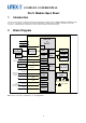
COMPANY CONFIDENTIAL 1 Part1. Module Spec Sheet Introduction The CX-series module is a single-board networked media player module, based on SMSC’s DM870A and DM875 media processors, and enables fast product developments with Ethernet, USB and optional WiFi connectivity. The module connects to standard legacy components in various audio, video/LCD and control formats. 2 Block Diagram JukeBlox Networked Media Module – CX Series DM870A or DM875 3.3V 1.2V 1.
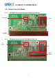
COMPANY CONFIDENTIAL 3 Board Pictures Please note that all production modules include the RF and top shield. The below top view has the shields temporarily removed to show the components. Also, please note that the 64-pin connector mounted on the module is the male gender. 3.1 Top View of CX Module 802.
COMPANY CONFIDENTIAL 3.2 3.2.1 Bottom View of CX Module CX Module Bottom View w/64-pin Low Density Connector LCD connector FLASH Low density connector 3.2.
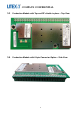
COMPANY CONFIDENTIAL 3.3 Production Module with Top and RF shields in place – Top View 3.
COMPANY CONFIDENTIAL 3.
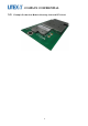
COMPANY CONFIDENTIAL Production Module with Bottom Shield (Part Numbers with a “B” after the configuration letter) 3.6 3.6.1 Including J3 Low Density 64-pin connector – Bottom View 3.6.
COMPANY CONFIDENTIAL 4 Ordering Guide CX Modules Configuration Matrix SKU Type IC's CX870-3B-D120 Module DM870A+T6201 Phase WiFi (onmodule PCB diveristy) Ext. Diverstiy Antennas (UFL Conn.s) One Ant. Planned Two Ant. X Eth USB Host X X Low Density 64-pin conn. HiDensity 120-pin Conn. X HiDensity LCD Conn. 64 MB 32MB SDRAM SDRAM X 16MB SDRAM 8MB SDRAM 1Gb NAND X 32MB NOR 8MB NOR Top Module Shield Bottom Module Shield X X 1.
COMPANY CONFIDENTIAL 5 Electrical Specifications Parameter State Model Power Supply Input Voltage VIN Logic Input high voltage Logic Input low voltage Logic Input threshold voltage Schmitt-trigger input low to high threshold voltage Schmitt-trigger input high to low threshold voltage Logic Output high voltage Logic Output low voltage Logic Low-level output current (VOL=0.4V) Logic High-level output current (VOH=2.4V) VIH VIL VIT min. 3.0 1.08 1.8 1.7 -0.3 1.29 VIT+ 1.58 1.65 1.71 V VIT- 0.
COMPANY CONFIDENTIAL 5.1 Absolute Maximum Ratings Parameter 3.3V Supply Voltage 1.2V Supply Voltage 1.9V Supply Voltage Logic Input Voltage Logic Output Voltage 5.2 Component Main Min -0.5 -0.5 -0.5 -0.5 -0.5 Max 4.6 1.8 2.2 6 4.
COMPANY CONFIDENTIAL 5.3 WiFi Specification (CX870 only) Feature WLAN Standards Frequency Band Modulation Transmission Speed Tx Power Description IEEE 802.11b IEEE 802.11g 2.412 – 2.472 GHz (2.4GHz ISM Band, 13 Channels) Channel 1 - Channel 13 North America FCC, Japan Telec, Europe ETSI 802.11b mode (DS-SS: IEEE 802.11b) 802.11g mode (OFDM: IEEE 802.11g) 802.11b mode 11Mbps, 5.5Mbps, 2Mbps, 1Mbps 802.11g mode 54Mbps, 48Mbps, 36Mbps, 24Mbps, 18Mbps, 12Mbps, 9Mbps, 6Mbps 802.11b mode: 16.5dBm, +/-1dB 802.
COMPANY CONFIDENTIAL 6 Regulatory Compliance and Quality Description Electromagnetic Compatibility (Prescan) Country USA Europe Radio Regulations (CX870 only) USA Japan Canada Europe New Zealand/Australia China Korea Compliance FCC CFR47 Part15B EN 55022 EN 55024 EN 61000-3-2 EN 61000-3-3 EN 61000-4-2 EN 61000-4-3 EN 61000-4-4 EN 61000-4-5 EN 61000-4-6 EN 61000-4-8 EN 61000-4-11 FCC Part 15C Telec IC RSS-210 CE AZ/NZS:4268 SRRC KCC Module Versions Passed B, D, F, H, I, J B B, D, F, H, I, J B SMSC do
COMPANY CONFIDENTIAL CX870-3BB Dipole 1.7 1.7 1.7 3.2 CX870-3HB Dipole 2 CX870-3HB PIFA 3 2.8 MSA-5403-2G4C1-A3, gray 300mm MSA-5103-2G4C1-A2, black 400mm MSA-5403-2G4C1-A2, gray 400mm WINiZEN W1E-WO-08 MAG. LAYERS EDA-8709-2G4C1-A66 3010000243ID (DA-E670) 3010000218ID (DA-E750) Notes about antenna changes: 1) Equivalent antennas from other manufacturers may be substituted, and then marketed without a Class II permissive change 2) Equivalent antennas must be of the same type (e.g.
COMPANY CONFIDENTIAL -Connect the equipment into an outlet on a circuit different from that to which the receiver is connected. -Consult the dealer or an experienced radio/ TV technician for help. CAUTION: Any changes or modifications not expressly approved by the grantee of this device could void the user's authority to operate the equipment. Labeling requirements This device complies with Part 15 of the FCC Rules.
COMPANY CONFIDENTIAL http://www.ic.gc.ca/eic/site/smt-gst.nsf/eng/sf08792.html Canada, avis d'Industry Canada (IC) Cet appareil numérique de classe B est conforme aux normes canadiennes ICES-003 et RSS-210. Son fonctionnement est soumis aux deux conditions suivantes : (1) cet appareil ne doit pas causer d'interférence et (2) cet appareil doit accepter toute interférence, notamment les interférences qui peuvent affecter son fonctionnement.
COMPANY CONFIDENTIAL Antenna List No. 1 2 3 4 Manufacturer Walsin Walsin Walsin Walsin 5 Walsin 6 Walsin Model No. RFDPA870920IMAB301 (200mm)(Main)(Aux) RFDPA870930IMAB301(300mm) (Main)(Aux) RFDPA870945IMAB301(450mm) (Main)(Aux) RFDPA870900SBAB801 + RFCBA100645SA6B301(450mm) (Main)(Aux) RFDPA870900SBAB801 + RFCBA100630SA6B301(300mm) (Main)(Aux) RFDPA870900SBAB801 + RFCBA100620SA6B301(200mm) (Main)(Aux) Peak Gain 2.14 dBi 1.2 dBi 1.16 dBi 0.2 dBi 0.3 dBi 0.
COMPANY CONFIDENTIAL 6.4 Magnetic Field Test Passes EN55022 and EN55024 (part of CE test) 6.5 MTBF >10000 hours 6.6 Mechanical Specifications Passes drop test according to I.E.C. 68-2-32, height 100 cm, 1 corner, 6 faces. Passes vibration test with sine, vertical, 60 minutes, 600 to 18000 cpm, 1G 6.7 Module Quality Defect Rate: < 1% AQL CR=0, MA=0.4, MI=0.
COMPANY CONFIDENTIAL 7 Board Dimensions and Weight 7.1 Top & Bottom View of CX870 Module without Bottom Shield 7.1.
COMPANY CONFIDENTIAL 7.2 Side View of CX870 module without Bottom Shield Note: 1. 2. 3. 4. 5. 6. 7. All dimensions are measured in millimetres (mm). PCB’s thickness: 1.00 +/- 0.10mm Tolerance: +/-0.10mm Outline Tolerance: +/-0.10mm NPTH Hole: +/-0.05mm PTH Hole: +/-0.075mm Connector positions, board dimensions, mounting hole positions and sizes are the same for all module variants. 8. Connector position tolerance: +/- 0.38mm 9.
COMPANY CONFIDENTIAL 7.2.2 7.3 Side View of CX870 Module with Bottom Shield part number CX870-3JB only 3D View of CX870 Module without Bottom Shield Note: A 3D file of the CX module in .stp format is available from the SMSC Customer Portal. 7.4 Module Weight CX870: 20g Note: Module weight applies to all versions of the module.
COMPANY CONFIDENTIAL 8 Connectors and Connections 8.1 WLAN UFL Antenna Connector (optional) The module includes two PCB strip antennas operated in diversity mode. Alternatively, one or two coaxial antenna connectors are provided for connecting external (to the module) antennas. The choice between using the strip antenna or using the coaxial sockets is a build option, determined by the position of surface mount capacitors on the module PCB.
COMPANY CONFIDENTIAL The pinout and signal names are shown on the next page. The following table provides an overview for the most important control and interface signals. 8.2.1 Pin Descriptions Signal(s) Type Description POWER VIN(+3.3V) VIN (+1.2V) VIN (+1.9V) 3V3RTC GND P P P P P Power supply input ; +3.3V. Power supply input ; +1.2V. Power Supply input; +1.9V for powering RF section. Make sure this is a clean supply. The RTC function is no longer supported. This pin should be left open.
COMPANY CONFIDENTIAL AUDIO AV2DATA0 O AV2CTRL0 O AV2CTRL1 O AV2CLK AV4DATA1 O O AV4DATA0 AV2DATA1 AOUTLP/AOUTLN, AOUTRP/AOUTRN I O O AV2DATA2 I AV2DATA3 I CONTROL NCS3 I PDOUT0 I VCO0 I AV3CLK O AV3CTRL0, AV3CTRL1 I/O NRESET_MOD I NPD_RF I I2S or left justified audio data output. Typically connected to external D/A converter input or to external DSP for further audio processing. Used for main left and right channel audio output data. See Note 3.
COMPANY CONFIDENTIAL ETHERNET ETH_RXN, ETH_RXP, ETH_TXN, ETH_TXP ETH_LED_SPEED, ETH_LED_ACT M O Ethernet signals between the PHY on the module and the external magnetics (transformer). See Note 4. Maximum bit rate is 100Mbps. 3.3V push-pull outputs (max. ±12mA) to drive the ethernet LEDs. 100Mbps speed mode and activity are indicated by the outputs being low. Connect to LEDs through 220ohm resistors. USB USB_DN, USB_DP M USB_VBUS M USBVBUSDRV O JTAG TMS,TCK,TDI, TDO I/O JTAG port for DM870A.
COMPANY CONFIDENTIAL GPIO (not already mentioned elsewhere in this table) A22 A23 NWAIT NCS2 VCO1 MIICRS MIICOL MIITXER MIITXCLK MII MIITXD0, MIITXD1, MIIRXD0, MIIRXD1 LCD LCDD0, LCDD1, LCDD2, LCDD3, LCDD4, LCDD5, LCDD6, LCDD7, LCDD8, LCDD9, LCDD10, LCDD11, LCDD12, LCDD13, LCDD14, LCDD15, LCD16, LCDD17, LCDCLK, LCDCTRL0, LCDCTRL1, LCDCTRL2, LCDCTRL3 O O I/O I I/O I/O I/O I/O I/O GPIO18 Reserved for NOR flash address A22. Leave open. GPIO-16 Reserved for NOR flash address A23. Leave open.
COMPANY CONFIDENTIAL Notes: 1. 2. 3. Signal type codes: I – 3.3V level Digital Logic Input into the DM870A O – 3.3V level Digital Logic Output from the DM870A IO – 3.3V level Digital Logic Input and Output (bi-directional) signal M – Miscellaneous, see text for description P – Power Supply For SPI timing diagram for eDMP applications, please see: BridgeCo_JB2x - DeviceControlProtocol_Registers_v_2_1.pdf, or later version.
COMPANY CONFIDENTIAL 8.2.2 Connector PIN Assignments J2 – Media Connector Function GPIO IC PIN Signal D15 D14 B16 C13 B14 A14 B13 SPI Debug UART SPI_E_NCS SPI_E_SDI GPIO-11 GPIO-09 D12 B12 D11 A11 C10 D10 A1 B1 E3 USB K4 L2 GPIO-16 GPIO-18 GPIO-14 GPIO-13 I2C SDA I2C SCL Video Output H17 H16 T3 U2 M3 M2 L1 M4 N1 N2 N3 T1 P4 R3 T2 U1 LRCK A/D data 1 A/D data 0 D/A data 1 D/A data 0 GND VIN (+3.3V) VIN (+3.3V) GND VIN (+1.2V) VIN (+1.2V) GND VIN (+1.
COMPANY CONFIDENTIAL J1 – LCD Connector Function GPIO IC PIN Signal LCD Interface V8 T8 V7 T7 V6 T6 V5 T5 U4 LCD Interface T10 T9 V9 GND LCDD0 LCDD2 LCDD4 LCDD6 LCDD8 LCDD10 LCDD12 LCDD14 LCDD16 GND LCDCLK LCDCTRL1 LCDCTRL3 GND PIN Number 1 3 5 7 9 11 13 15 17 19 21 23 25 27 29 2 4 6 8 10 12 14 16 18 20 22 24 26 28 30 Signal GND LCDD1 LCDD3 LCDD5 LCDD7 LCDD9 LCDD11 LCDD13 LCDD15 LCDD17 GND LCDCTRL0 LCDCTRL2 GND GND IC PIN GPIO Function U8 R8 U7 R7 U6 R6 U5 V4 V3 LCD Interface R9 U9 LCD Interfac
COMPANY CONFIDENTIAL 8.2.
COMPANY CONFIDENTIAL 9.1.1 Power up, Reset and Power Down Timing Voltage Power Up Power Down +3.3V +1.2V 0V < 300ms NRESET_MOD >= 2ms Time 9.2 RF Considerations Note that overall system, RF and WiFi performance is significantly affected by the product design, environment and the application. It is the responsibility of the product designer to ensure proper system level shielding (if required) and to verify performance and fitness for the given product features and applications.
COMPANY CONFIDENTIAL 10 Revision Control Revision Date / Author Details of Change Reason for Change V2.8 (093012) Sept 30, 2012 / SHs Updated Section 4 Ordering Guide with 2 new rows for CX870-3LB & CX870-3MB and moved the row for CX870-3KB to be with them. New SKUs available. V2.8 (092412) Sept 24, 2012 / SHs Updated cover page with new Microchip logo; removed SMSC logo from header; removed SMSC logo & address from legal text (page 2); added info about Microchip to legal text; updated © to 2012.
COMPANY CONFIDENTIAL Revision Date / Author Details of Change Reason for Change (061312) 2012 / SHs CX870-3B, 3H, 3I, 3J shaded. bottom shield, so modules without a bottom shield are now marked as "NOT TO BE USED FOR NEW/STANDARD MP DESIGNS" by shading the rows in the Ordering Guide table for those modules with no bottom shield. V2.6 (050812) May 8, 2012 / SHs Removed entries in ‘8MByte NOR’ column for modules 3A, 3B, 3D, 3DS in Section 4 Ordering Guide Correction. V2.
COMPANY CONFIDENTIAL Revision Date / Author Details of Change Reason for Change V2.4 (031212) March 12, 2012 / SHs Added Section 3.6 Production Module with Bottom shield (Part Numbers with a "B" after the configuration letter) Show module versions with bottom shield. Added Section 3.6.1 Including J3 Low Density 64-pin connector - Bottom View Show bottom shield. Added Section 3.6.2 Including J2 High Density 120-pin connector - Bottom View Show bottom shield.
COMPANY CONFIDENTIAL Revision V2.0 c V2.0 b Date / Author Sept. 14, 2011 / SHs Sept. 10, 2011 / SHs Details of Change Reason for Change Section 6 reverted back to original numbering the need to redo certifications. Updated Notes 11 & 12 in Section 8.2.1 Pin Descriptions with updated Customer Portal information Easier to access URL directly. Updated Table of Contents Keep TOC aligned with actual content. Updated font styling of Table of Contents Easier to read.
COMPANY CONFIDENTIAL Revision V1.9 b V1.9 a V1.8 a V1.8 Date / Author July 28, 2011 / SHs July 25, 2011 / SHs July 10, 2011 / SHs July 5, 2011 / SHs Details of Change Reason for Change Updated Antenna Configuration entry in Section 4.1 Part number syntax Updated Section 4.
COMPANY CONFIDENTIAL Revision V1.7 c V1.7 b V1.7 a V1.7 V1.6 d V1.
COMPANY CONFIDENTIAL Revision Date / Author V1.6 b February 23, 2011 / SHs V1.6 February 11, 2011 / SHs Details of Change Reason for Change Updated “J3-Low density connector” pin description table Updated “GPIO Assignments” table Entirely updated the “Ordering Guide” Added a Note to the “Ordering Guide” Updated the subsection titles for the “Board Pictures” section Updated the Block Diagram – changed ‘WiFi Antenna’ to ‘Ext. Antenna’ V1.
COMPANY CONFIDENTIAL Revision V1.
COMPANY CONFIDENTIAL Part2.
COMPANY CONFIDENTIAL 2 RFDPA870945IMAB301 43