
DVD Recorder User Manual

10
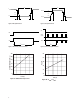
Recommended Reow Prole
Process Zone Symbol ∆T Maximum ∆T/∆time
Heat Up P1, R1 25°C to 160°C 4°C/s
Solder Paste Dry P2, R2 160°C to 200°C 0.5°C/s
Solder Reow P3, R3 200°C to 255°C (260°C at 10 seconds max) 4°C/s
P3, R4 255°C to 200°C -6°C/s
Cool Down P4, R5 200°C to 25°C -6°C/s
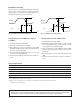
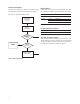
The reow prole is a straight-line representation of a
nominal temperature prole for a convective reow sol-
der process. The temperature prole is divided into four
process zones, each with dierent ∆T/∆time temperature
change rates. The ∆T/∆time rates are detailed in the
above table. The temperatures are measured at the com-
ponent to printed circuit board connections.
In process zone P1, the PC board and HSDL-3220 cas-
tellation pins are heated to a temperature of 160°C to
activate the ux in the solder paste. The temperature
ramp up rate, R1, is limited to 4°C per second to allow
for even heating of both the PC board and HSDL-3220
castellations.
Process zone P2 should be of sucient time duration
(60 to 120 seconds) to dry the solder paste. The tem-
perature is raised to a level just below the liquidus point
of the solder, usually 200°C (392°F).
Process zone P3 is the solder reow zone. In zone P3,
the temperature is quickly raised above the liquidus
point of solder to 255°C (491°F) for optimum results. The
dwell time above the liquidus point of solder should be
between 20 and 60 seconds. It usually takes about 20
seconds to assure proper coalescing of the solder balls
into liquid solder and the formation of good solder
connections. Beyond a dwell time of 60 seconds, the
intermetallic growth within the solder connections be-
comes excessive, resulting in the formation of weak and
unreliable connections. The temperature is then rapidly
reduced to a point below the solidus temperature of the
solder, usually 200°C (392°F), to allow the solder within
the connections to freeze solid.
Process zone P4 is the cool down after solder freeze.
The cool down rate, R5, from the liquidus point of the
solder to 25°C (77°F) should not exceed 6°C per second
maximum. This limitation is necessary to allow the PC
board and HSDL-3220 castellations to change dimen-
sions evenly, putting minimal stresses on the HSDL-3220
transceiver.
0
t-TIME (SECONDS)
T – TEMPERATURE – ( C)
230
200
160
120
80
50 150100 200 250 300
180
220
255
P1
HEAT
UP
P2
SOLDER PASTE DRY
P3
SOLDER
REFLOW
P4
COOL DOWN
25
R1
R2
R3
R4
R5
60 sec.
MAX.
ABOVE
220 C
MAX. 260 C