
DVD Recorder User Manual

16
Appendix D: Window Designs for HSDL-3220
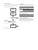
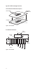
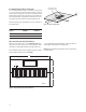
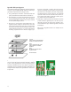
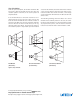
Figure 19. Window design diagram.
Optical port dimensions for HSDL-3220
To ensure IrDA compliance, some constraints on the
height and width of the window exist. The minimum
dimensions ensure that the IrDA cone angles are met
without vignetting. The maximum dimensions minimize
the eects of stray light. The minimum size corresponds
to a cone angle of 30° and the maximum size corre-
sponds to a cone angle of 60°.
In the gure below, X is the width of the window, Y is
the height of the window and Z is the distance from
the HSDL-3220 to the back of the window. The distance
from the center of the LED lens to the center of the pho-
todiode lens, K, is 5.1mm. The equations for computing
the window dimensions are as follows:
X = K + 2*(Z+D)*tanA
Y = 2*(Z+D)*tanA
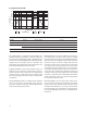
The above equations assume that the thickness of the
window is negligible compared to the distance of the
module from the back of the window (Z). If they are com-
parable, Z' replaces Z in the above equation. Z' is dened
as
Z' = Z + t/n
where ‘t’ is the thickness of the window and ‘n’ is the re-
fractive index of the window material.
The depth of the LED image inside the HSDL-3220, D,
is 3.17 mm. ‘A’ is the required half angle for viewing. For
IrDA compliance, the minimum is 15° and the maximum
is 30°. Assuming the thickness of the window to be neg-
ligible, the equations result in the following tables and
graphs.
D
Z
K
A
IR TRANSPARENT
WINDOW
OPAQUE
MATERIAL
OPAQUE
MATERIAL
IR TRANSPARENT WINDOW
X
Y