
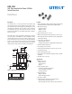
DVD Recorder User Manual

4
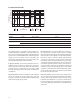
Absolute Maximum Ratings
For implementations where case to ambient thermal resistance is ≤50°C/W.
Parameter Symbol Min. Max. Units Conditions
Storage Temperature T
S
-40 +100 °C
Operating Temperature T
A
-25 +70 °C
LED Anode Voltage V
LEDA
0 6.5 V
Supply Voltage V
CC
0 6.5 V
Input Voltage: TXD, SD/Mode V
I
0 6.5 V
Output Voltage: RXD V
O
0 6.5 V
DC LED Transmit Current I
LED
(DC) 50 mA
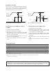
Average Transmit Current I
LED
(PK) 200 mA ≤ 90µs pulse width
≤25% duty cycle
Recommended Operating Conditions
Parameter Symbol Min. Typ. Max. Units Conditions
Supply Voltage V
CC
2.7 3.6 V
Input/Output Voltage IOVcc 1.8 Vcc V
Logic Input Voltage Logic High V
IH
IOV
cc
– 0.5 IOV
cc
V
for TXD, SD/Mode
Logic Low V
IL
0 0.4 V
Logic High E
IH, min
0.0081 mW/cm
2
9.6kbit/s ≤ in-band signals
≤1.152 Mbit/s
[14]
Receiver Input Irradiance 0.020 mW/cm
2
1.152 Mbit/s < in-band signals
≤ 4.0 Mbit/s
[14]
E
IH, max
500 mW/cm
2
9.6 kbit/s ≤ in-band signals
≤ 4.0 Mbit/s
[14]
Logic Low E
IL
0.3 µW/cm
2
For in-band signals
[14]
LED (Logic High) Current I
LEDA
150 mA
Pulse Amplitude
Receiver Data Rate 0.0096 4.0 Mbit/s
Note :
14. An in-band optical signal is a pulse/sequence where the peak wavelength, λp, is dened as 850 ≤ λp ≤ 900 nm, and the pulse characteristics
are compliant with the IrDA Serial Infrared Physical Layer Link Specication v1.4.