
Datasheet

LITE-ON TECHNOLOGY CORPORATION
Pr o p e r t y o f L i t e - O n O n ly
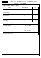
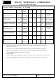
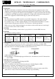
Electrical Optical Characteristics At Ta=25
℃
Parameter
Symbol
Part No.
LTST-
Min.
Typ.
Max.
Unit
Test Condition
Luminous Intensity
IV
C170TGKT
71.0
-
450.0
mcd
IF = 20mA
Note 1
Viewing Angle
2
θ
1/2
C170TGKT
130
deg
Note 2 (Fig.6)
Peak Emission Wavelength
λ
P
C170TGKT
530
nm
Measurement
@Peak (Fig.1)
Dominant Wavelength
λ
d
C170TGKT
525
nm
IF = 20mA
Note 3
Spectral Line Half-Width
Δλ
C170TGKT
35
nm
Forward Voltage
VF
C170TGKT
2.80
3.20
3.60
V
IF = 20mA
Reverse Current
IR
C170TGKT
10
μ
A
VR = 5V
Notes: 1. Luminous intensity is measured with a light sensor and filter combination that approximates the
CIE eye-response curve.
2.
θ
1/2 is the off-axis angle at which the luminous intensity is half the axial luminous intensity.
3. The dominant wavelength,
λ
d is derived from the CIE chromaticity diagram and represents the
single wavelength which defines the color of the device.
4. Caution in ESD:
Static Electricity and surge damages the LED. It is recommend to use a wrist band or anti-electrostatic
glove when handling the LED. All devices, equipment and machinery must be properly grounded.
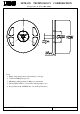
Part No. : LTST-C170TGKT
Page : 4 of 11
BNS-OD-C131/A4