
Instructions / Assembly

A division of
Une division de
Una división de
Copyright © 2020, Liteline Corporation. All rights reserved.
LITELINE CORPORATION
P 416-996-1856 | 1-866-730-7704
F 905-709-5255 | 1-888-738-9736
EN
IMPORTANT: Read all instructions before installing fi xtures.
Retain for future reference.
SAFETY: For your safety, this fi xture must be wired in
accordance to local electrical codes and ordinances. All work
should be done by a qualifi ed electrician.
WARNING: Make certain power is OFF from the electrical panel
before starting installation or attempting any maintenance.
Indoor installation only.
TOOLS REQUIRED:
• Drywall Saw
• Measuring Tape
• Electrical Wiring (use type and gauge suitable for
application to connect the fi xtures)
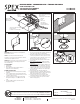
ASSEMBLY INSTRUCTIONS:
1. Turn power OFF from the electrical panel before starting
installation.
2. Locate a suitable position to place the fi xture and open a
hole in accordance to the cut-hole dimensions (refer to Hole
Cut Table for appropriate size).
3. Run the electrical wire from the switch (power supply)
through the mounting hole – use NMD90 Romex or BX
cable.
4. Open the hardwire box swing cover and remove the
appropriate knockout(s).
5. Insert the electrical supply cable through the knockout and
secure with a cable connector (sold separately).
6. Wire box using supplied quick connect push-in terminals.
Connect green ground wire of cable to green wire on box.
Connect white wire of cable to white wire of box. Connect
black wire of cable to black wire of box (Fig. 1).
7. Place all wiring and connections back in to the box and
close the cover
8. New construction applications: Hardwire box shall be
fi rmly secured to studs, joists, or similar fi xed structural
units (Fig. 2).
Remodel applications: Do not require the hardwire box to
be fi rmly secured after the mounting plates, studs, joists,
or structural units that have been concealed. Snap off the
hardwire box tabs (Fig. 3), then insert into ceiling (Fig. 4).
9. Connect hardwire box to fi xture by connecting the quick
disconnect (Fig. 4).
10. Remove magnetic trim if attached to fi xture base.
11. Push spring loaded clips on the fi xture upwards and insert
fi xture base in to the mounting hole. Release the clips and
fi xture will be pulled fl ush to the ceiling (Fig. 5).
12. Select desired CCT (2700K, 3000K, 3500K, 4000K,
5000K). Attach magnetic trim to the fi xture base (Fig. 6).
13. Once assembly is complete, turn on power to confi rm
fi xture is working properly.
1
2
2700K
3000K
3500K
4000K
5000K
Fig. 4 Fig. 5
Fig. 6
REV 9.15.20
Power supply
Bloc d'alimentation
Fuente de alimentación
Black wire
Fil noir
Cable negro
White wire
Fil blanc
Cable blanco
Quick connect push-in terminals
Bornes à bouton
Terminales de conexión rápida
Quick connect push-in terminals
Bornes à bouton
Terminales de conexión rápida
Cable to fi xture
Câble sur le montage
Cable a lámpara
Green wire
Fil vert
Cable verde
Fig. 1 Fig. 2
Fig. 3
SL-SLM4-CCT5
SL-SLM6-CCT5
RECESSED LIGHTING • LUMINAIRE ENCASTRE • LÁMPARAS EMPOTRADAS
COLOR SELECTABLE SLIM
SLIM COULEUR SÉLECTIONNABLE
SLIM COLOR SELECCIONABLE
For more information on our lifetime warranty, please visit www. trenzlighting.com/goldlabel
Pour plus d'informations sur notre garantie à vie, s'il vous plaît visitez www. trenzlighiting.com/goldlabel
Para obtener más información sobre nuestra garantía de por vida, visite www. trenzlighiting.com/goldlabel
Hole Cut Size / Taille Trou Découpé / Tamaño de
corte del Orifi cio
SL-SLM4-CCT5 Ø 4¼ " (108mm)
SL-SLM6-CCT5 Ø 6¼ " (159mm)