Strip Fixture Motion Sensor Kit SFAS50 Installation Instructions For Strip Fixtures PLEASE READ THESE INSTRUCTIONS BEFORE INSTALLATION
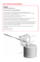
SAFETY INSTRUCTIONS AND WARNINGS WARNING: READ CAREFULLY BEFORE INSTALLING RETAIN THESE INSTRUCTIONS FOR FUTURE REFERENCE. Sensor must be wired in accordance with the National Electrical Code and all applicable local codes. Risk of fire or electric shock. Sensor installation requires knowledge of luminaire electrical systems. If not qualified, do not attempt installation. Contact a qualified electrician. Be certain electrical power is OFF before and during installation and maintenance.
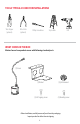
12 13 TOOLS TYPICALLY USED FOR INSTALLATIONS Wire Stripper (optional) Wire Cutter (optional) Phillips Screwdriver Step Ladder Drill WHAT COMES IN THE BOX Motion Sensor base product comes with following standard parts: (1) Sensor (1) Bracket (1) Split-Grommet (3) Self-tapping screws (3) Mounting screws Before Installation, carefully remove all parts from the packaging. Inspect product for defects due to shipping.
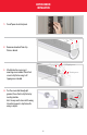
MOTION SENSOR INSTALLATION 1. Turn off power at electrical panel. 2. Remove one knock out from strip fixture as desired. Self-tapping screws 3. Attach bracket to sensor using 3 mounting screws included. Then attach sensor to strip fixture using 3 selftapping screws included. Mounting screws 4. Pass the sensor cable through split grommet, then attach to strip fixture by inserting into hole. Note: You may want to leave slack for wiring, then attach grommet to strip fixture after wiring is complete.
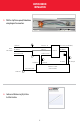
MOTION SENSOR INSTALLATION 5. With the strip fixture opened, follow below wiring diagram for connections. OPTION A: Wiring Diagram for Strip Fixture and Sensor INPUT CABLE WIRE L (Black) Brown L in N (White) Blue N Green Ground Yellow L out N (White) D+ Red (0-10V Dim) SENSOR D- Gray L (Black) DRIVER OF LAMP (STRIP FIXTURE) Green Ground WIRE NUT 05/10/2017 6. Continue installation using Strip Fixture Install instructions.
MOTION SENSOR INSTALLATION 7. To set sensor functionality, remove screw from plastic cover on sensor and then unscrew top cover from sensor assembly. You will see dip switch. MC031V SENSOR SETTINGS By setting the DIP switch, sensor data can be precisely set for each specific application.
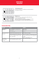
MOTION SENSOR INSTALLATION ON ON 8 ON — ON — I II III IV I II III IV 10 ON — ON — Stand-by dimming level 9 ON ON — — 11 ON ON — — 50% 30% 20% 10% 12 ON Disable — 200lux — 100lux — 50lux Determines the light level you would like to have after the hold time in the long absence of people. Daylight sensor The sensor can be set to only allow the lamp to illuminate below a defined ambient brightness threshold.
Thank you for choosing 6969 W. 73rd Street Bedford Park, IL 60638 WWW.LITETRONICS.COM CustomerService@Litetronics.