ITEM #0889801 #0889802 #0889803 BAYOU CREEK CEILING FAN MODEL #CAF48BNK5LRC #CAF48OSB5LRC #CAF48LW5LRC Español p. 22 ATTACH YOUR RECEIPT HERE 4009654 Purchase Date Questions, problems, missing parts? Before returning to your retailer, call our customer service department at 1-800-527-1292, 8:30 a.m. - 5 p.m.
TABLE OF CONTENTS Safety Information ................................................................................................................2 Package Contents ................................................................................................................4 Hardware Contents ...........................................................................................................................5 Preparation ...........................................................................
SAFETY INFORMATION WARNING To reduce the risk of fire, electrical shock or personal injury, mount fan to outlet box marked "ACCEPTABLE FOR FAN SUPPORT OF 35 LBS. (15.9 KG) OR LESS" and use mounting screws provided with the outlet box. Most outlet boxes commonly used for the support of lighting fixtures are not acceptable for fan support and may need to be replaced. Consult a qualified electrician if in doubt.
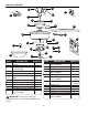
PACKAGE CONTENTS Y C R Z V A X W B E G D J U T S N H M K F L Q P I O PART DESCRIPTION QUANTITY A Downrod 1 B Canopy 1 C Mounting Bracket 1 (preassembled) D Motor Housing 1 E Yoke Cover 1 F Light Kit Fitter 1 G Blade 5 H Bulb 2 I Finial Plate (preassembled) 1 J Blade Arm 5 K Hex Nut (preassembled) 2 L Lock Washer (preassembled) 1 M Switch Housing Cap 1 (preassembled) PART DESCRIPTION QUANTITY N Switch Housing Cap Screw 3 (preassembled) O Finial (preassembled) 1 P Glass Shade 1 Q Rubber Wash
HARDWARE CONTENTS (shown actual size) AA Cap Qty. 1 BB CC Blade Screw Fiber Blade Washer Qty. 15 + 1 extra DD Wire Connector Qty. 15 + 1 extra Qty. 4 PREPARATION Before beginning assembly of product, make sure all parts are present. Place motor on carpet or on foam to avoid damage to finish. Compare parts with package contents list and hardware contents list. If any part is missing or damaged, do not attempt to install, operate or assemble the product.
INITIAL INSTALLATION 1. Turn off circuit breakers and wall switch to the fan supply line leads. 1 DANGER: Failure to disconnect power supply prior to installation may result in serious injury or death. ON ON FF OFF O 2. Determine mounting method to use. A. Downrod mount (standard or angled ceiling) B. Closemount (standard ceiling only) IMPORTANT: If using the angle mount, check to make sure the ceiling angle is not steeper than 19°. 2 19° max.
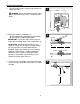
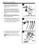
INITIAL INSTALLATION 4a. Loosen canopy mounting screws (Z) in slotted holes of canopy (B) and remove the other two canopy mounting screws (Z) and star washers (Y). Save for later use. 4a Y Z C Remove mounting bracket (C) from canopy (B). B 4b. Secure mounting bracket (C) to outlet box (not included) using screws, spring washers and flat washers provided with the outlet box. NOTE: It is very important you use the proper hardware when installing the mounting bracket (C) as this will support the fan.
DOWNROD-STYLE FAN MOUNTING 1. Remove pin (W) and clip (X) from downrod (A). Partially loosen preassembled set screws and nuts in motor housing yoke at top of motor housing (D). 1 X Sid ev A iew W Set Screw and Nut Yoke D 2. Insert downrod (A) through canopy (B) and yoke cover (E). Then, thread wires from motor housing (D) up through downrod (A). 2 A B E 3. Slip downrod (A) into yoke, align holes and re-install pin (W) and clip (X). Tighten set screws and then tighten nuts.
DOWNROD-STYLE FAN MOUNTING 4. Depending on the length of downrod you use, you may need to cut the lead wires back to simplify the wiring. If you decide to cut back the lead wires, it is suggested you do so in the following manner: 4 8 in. Take the lead wires and make sure you have pulled them all the way through the top of the downrod. Start at the TOP of the hanging ball on the downrod and measure 8 in. of lead wire, and then cut the excess wire off with wire cutters (not included).
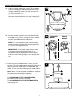
CLOSEMOUNT-STYLE FAN MOUNTING 1. Remove preassembled canopy cover from bottom of canopy (B). NOTE: It may be necessary to use the handle end of a screwdriver (not included) to remove the canopy cover by tapping on the canopy cover from the inside of the canopy (B). 1 B NOTE: The downrod (A), yoke cover (E) and canopy cover are not used in this type of installation. Canopy Cover 2. Remove every other preassembled screw and lock washer from top of motor housing (D). 2 B J D D 3.
CLOSEMOUNT-STYLE FAN MOUNTING 4. Temporarily hang fan on the tab on the mounting bracket (C) using one of the non-slotted holes in the canopy (B). 4 C Tab Hole B WIRING WARNING: To reduce the risk of fire, electrical shock or personal injury, each wire connector provided with this fan is designed to accept only one 12-gauge house wire and one lead wire from the fan.
WIRING 1. Make the necessary wiring connections for remote control operation as detailed below and in the figure. For each wire connection, use one of the wire connectors (DD), making sure to screw wire connector (DD) on in a clockwise direction. 1 WHITE SUPPLY WIRE BLACK SUPPLY WIRE BLUE WHITE BLACK GROUND (GREEN OR BARE) GROUND (GREEN OR BARE) WHITE BLACK FROM FAN CAUTION: Assistance from another person is recommended for this step.
WIRING 3. Gently slide remote control receiver (V) flat-side up into mounting bracket (C). Turn spliced/taped wires upward and gently push wires and wire connectors (DD) into outlet box. Let antenna from remote control receiver (V) hang to the side. 3 C Antenna NOTE: The remote control included with this fan meets the following requirements: a. Not for use with solid state fans. b. Electrical rating: 120V / 60 Hz; motor amps:1.25 MAX.
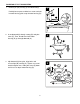
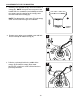
FINAL INSTALLATION 3. Attach blade arms (J) to the bottom of motor housing (D) with motor screws (S) and washers (T) previously removed (Step 5, page 7). Tighten motor screws (S) securely. 3 D Note: Make sure to completely secure each blade arm (J) before proceeding to the next. G If you do NOT wish to use the light kit, skip to INSTALLING FAN WITHOUT LIGHT KIT on page 16. T If you DO wish to use the light kit, proceed to Step 4. 4.
FINAL INSTALLATION 6. Remove finial (O), finial plate (I), hex nut (K) and rubber washer (Q) from the threaded rod at the bottom of the light kit fitter (F). Save for later use. 6 F Threaded Rod Q K I O 7. Install bulbs (H). 7 CAUTION: When replacing bulb(s), allow bulb(s) and glass shade to cool down before touching. H 8. Place rubber washer (Q) inside glass shade (P) over center hole. Align hole in center of glass shade (P) with threaded rod on light kit fitter (F).
FINAL INSTALLATION 9. If you wish to use the remote control bracket from remote pack (U), install screws from remote pack (U) through bracket and into the desired installation site. The remote control transmitter from remote pack (U) rests inside the bracket. 9 Wall Bracket Screws Remote Control Bracket INSTALLING FAN WITHOUT LIGHT KIT 1.
OPERATING INSTRUCTIONS CAUTION: The remote control transmitter can be programmed to multiple receivers or fans. If this is not desired, turn wall switch off to any other programmable receiver or fan. FCC Compliance Notice for Remote Control Modifications not approved by the party responsible for compliance could void the user's authority to operate the equipment. *NOTE: This equipment has been tested and found to comply with the limits for a Class B digital device, pursuant to Part 15 of the FCC Rules.
OPERATING INSTRUCTIONS 2. Restore electrical power. Within 30 seconds of restoring electrical power, press and hold the “0” button on the remote control transmitter for 5 seconds or until light on the fan blinks twice. Use the remote control transmitter to test the light and fan functions to confirm the learning process is complete. 2 NOTE: Remove protective covering from front of remote control transmitter and discard.
OPERATING INSTRUCTIONS 4a. In warmer weather, setting the reverse switch in the DOWN position will result in downward airflow creating a wind chill effect. 4a 4b 4b. In cooler weather, setting the reverse switch in the UP position will result in upward airflow that can help move stagnant, hot air off the ceiling area. 4c. IMPORTANT: Reverse switch must be set either completely UP or completely DOWN for fan to function. If the reverse switch is set in the middle position, fan will not operate.
TROUBLESHOOTING WARNING: Before beginning work, shut off the power supply to avoid electrical shock. PROBLEM Fan does not move. POSSIBLE CAUSE 1. Reverse switch not engaged. 2. Power is off or fuse is blown. 3. Faulty wire connection. 4. Learning code process between fan and remote control transmitter may not have been successful and learning code was not activated. Noisy operation. 1. Blades are loose. 2. Cracked blade. 3. Full range dimmer switch. 1. Tighten all blade screws. 2. Replace blade. 3.
LIMITED LIFETIME WARRANTY The distributor warrants this fan to be free from defects in workmanship and materials present at time of shipment from the factory for Lifetime limited from the date of purchase. This warranty applies only to the original purchaser. The distributor agrees to correct any defect at no charge or, at our option, replace the ceiling fan with a comparable or superior model. To obtain warranty service, present a copy of your sales receipt as proof of purchase.