READ THESE INSTRUCTIONS AND SAVE THEM FOR FUTURE USE Installation Guide For Models: CSU44BNK5C1 CSU44HRB5C1 Table of Contents: Safety Tips. pg. 1 Unpacking Your Fan. pg. 2 Parts Inventory. pg. 2 Installation Preparation. pg. 3 Hanging Bracket Installation. pg. 3 Fan Assembly. pg. 4 Wiring. pg. 5 Motor Housing Assembly. pg. 6 Blade Assembly. pg. 6 Light Kit Assembly (Optional). pgs. 7 - 9 Testing Your Fan. pg. 10 Troubleshooting. pg. 11 Warranty. pg. 11 Parts Replacement. pg.
SAFETY TIPS. WARNING: To reduce the risk of electrical shock, turn off the electricity to the fan at the main fuse box or circuit panel before you begin the fan installation or before servicing the fan or installing accessories. 1. READ ALL INSTRUCTIONS AND SAFETY INFORMATION CAREFULLY BEFORE INSTALLING YOUR FAN AND SAVE THESE INSTRUCTIONS. CAUTION: To avoid personal injury, the use of gloves may be necessary while handling fan parts with sharp edges. 2. 3. 4.
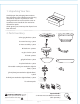
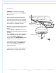
1. Unpacking Your Fan. Carefully open the packaging. Remove items from Styrofoam inserts. Remove motor housing and place on carpet or Styrofoam to avoid damage to finish. Do not discard fan carton or Styrofoam inserts should this fan need to be returned for repairs. Check against parts inventory that all parts have been included. 2. Parts Inventory. a b a. hanging bracket. 1 piece b. motor housing. 1 piece c. motor assembly. 1 piece c d. blade arm. 5 pieces d e. glass shade. 1 piece f. blade.
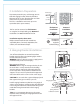
3. Installation Preparation. To prevent personal injury and damage, ensure that the hanging location allows the blades a clearance of 7ft. (2.13m) from the floor and 30in. (76cm) from any wall or obstruction. This fan is suitable for room sizes up to 225 square feet (20.9 square meters). 12 ft. - 15 ft. (3.66m - 4.57m) blade edge 30 inches 7 feet (76cm) (2.13m) 12 ft. - 15 ft. (3.66m - 4.
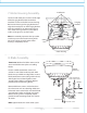
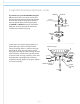
. Fan Assembly. Install ball end of motor assembly into hanging bracket opening. Align slot in ball with tab in hanging bracket. hanging bracket DANGER: Failure to align slot in ball with tab in hanging bracket may result in serious injury or death. tab slot ball motor assembly To ensure the safety of the installation and to prevent the motor assembly from becoming or coming loose, use the plastic lock tab. Slide plastic lock tab under bracket tabs so that it will snap into place.
. Wiring. CAUTION: Be sure outlet box is properly grounded and that a ground wire (GREEN or Bare) is present. Make sure all electrical connections comply with Local Codes or Ordinances and the National Electrical Code. If you are unfamiliar with electrical wiring or if the house/building wires are different colors than those referred to below, please use a qualified electrician.
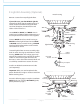
metal posts 7. Motor Housing Assembly. Locate 4 small metal posts on the outside edge of the hanging bracket. Now, locate the 4 metal bars on the inside of the motor housing. Raise motor housing to hanging bracket and align the 4 metal posts on the hanging bracket with the 4 metal bars on the motor housing. Turn motor housing clockwise, to the RIGHT, until it no longer turns so that it locks.
9. Light Kit Assembly (Optional). motor housing Remove 3 screws from top of light kit fitter. motor housing If you wish to use your fan WITH the light kit, remove finial, finial plate, threaded washer and rubber washer from bottom of light kit fitter. Save finial, finial plate, threaded washer and rubber washer for later use. Locate BLUE (or BLACK) and WHITE wires in switch housing labeled FOR LIGHT. Remove and discard plastic that hold these 2 wires together.
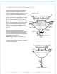
. Light Kit Assembly (Optional). (cont). Locate rubber washer, threaded washer, finial plate, and finial that were removed on the previous page. Place rubber washer inside glass shade over center hole. Raise glass shade in order to guide pull chains through corresponding holes at the bottom of the glass shade. Align hole in center of glass shade with threaded rod on light kit fitter and push up gently until threaded rod comes through hole.
9. Light Kit Assembly (Optional). (cont). If you wish to use your fan WITHOUT the light kit, remove the hex nut and lock washer from the threaded rod at the top of the light kit fitter. Unscrew the switch housing cap to remove it from the light kit fitter, and then gently feed the BLACK and WHITE wires from the light kit fitter (one at a time) through the hole in the middle of the switch housing cap.
10. Testing Your Fan. It is recommended that you test fan before finalizing installation. Restore power from circuit box and light switch (if applicable). Test fan speeds with the pull chain on switch housing. Start at the OFF position (no blade movement). First pull will set the fan to HI. Second pull will set the fan to MEDIUM. Third pull will set the fan to LOW. Fourth pull will again set the fan to OFF setting. If applicable, test light with pull chain in the middle (diagram 1).
Troubleshooting. Warranty. WARNING: Failure to disconnect power supply prior to troubleshooting any wiring issues may result in serious injury. LITEX LIFETIME LIMITED WARRANTY: LITEX INDUSTRIES, LTD. warrants this fan to the original household purchaser for indoor use under the following provisions: 1-YEAR WARRANTY: LITEX INDUSTRIES, LTD. will replace or repair any fan which has faulty performance due to a defect in material or workmanship.