READ THESE INSTRUCTIONS AND SAVE THEM FOR FUTURE USE Federal regulations require ceiling fans with light kits manufactured or imported after January 1, 2009, to limit total wattage consumed by the light kit to 190W. Therefore, this fan is equipped with a wattage limiting device. . O . F.P t Only Installation Guide en m e lac P r Fo For Model: E-BR52LPN5C1S Table of Contents: Safety Tips. pg. 1 Unpacking Your Fan. pg. 2 Parts Inventory. pg. 2 Installation Preparation. pg.
SAFETY TIPS. WARNING: To reduce the risk of electrical shock, turn off the electricity to the fan at the main fuse box or circuit panel before you begin the fan installation or before servicing the fan or installing accessories. 1. READ ALL INSTRUCTIONS AND SAFETY INFORMATION CAREFULLY BEFORE INSTALLING YOUR FAN AND SAVE THESE INSTRUCTIONS. CAUTION: To avoid personal injury, the use of gloves may be necessary while handling fan parts with sharp edges. 2. 3. 4.
1. Unpacking Your Fan. Carefully open the packaging. Remove items from Styrofoam inserts. Remove motor housing and place on carpet or Styrofoam to avoid damage to finish. Do not discard fan carton or Styrofoam inserts should this fan need to be returned for repairs. Check against parts inventory that all parts have been included. a 2. Parts Inventory. b a. canopy. 1 piece b. hanging bracket. 1 piece c d c. 6in. downrod and hanging ball. 1 piece d. canopy cover. 1 piece e f e. motor housing.
3. Installation Preparation. 12ft. - 20ft. (3.66m - 6.1m) blade edge 30 inches 7 feet (76 cm) (2.13m) To prevent personal injury and damage, ensure that the hanging location allows the blades a clearance of 7ft. (2.13m) from the floor and 30in. (76cm) from any wall or obstruction. This fan is suitable for room sizes up to 400 square feet (37.2 square meters). 12ft. - 20ft. (3.66m - 6.
. Fan Assembly. If you wish to extend the hanging length of your fan, set screw you must remove the hanging ball from the 6in. downrod provided to use with an extended downrod (sold separately). [If you wish to use the 6in. downrod, please proceed to instructions following the dotted line below.] set screw hole stop pin hanging ball To remove hanging ball, loosen set screw on hanging ball, lower hanging ball and remove stop pin.
5. Fan Assembly. (cont.) With the hanging bracket secured to the outlet box and able to support the fan, you are now ready to hang your fan. Grab the fan firmly with two hands. Slide downrod through opening in hanging bracket and let hanging ball rest on the hanging bracket. Turn the hanging ball slot until it lines up with the hanging bracket tab. Tip: Seek the help of another person to hold the stepladder in place and to lift the fan up to you once you are set on the ladder.
. Canopy Assembly. Locate 2 screws on underside of hanging bracket and remove screw closest to the open end of the hanging bracket. Partially loosen the other screw. Lift canopy to hanging bracket. Place rounded part of slotted hole in canopy over loosened screw in hanging bracket and push up. Twist canopy to lock. Re-insert screw that was removed and then tighten both screws securely.
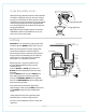
9. Light Kit Assembly. motor housing Remove 1 screw from motor plate on underside of motor housing and partially loosen the other 2 screws. Align slotted holes in center of fitter plate with loosened screws in motor plate, allowing the male plug from motor housing to come through hole in middle of fitter plate. Twist fitter plate to lock. Re-insert screw that was previously removed and securely tighten all 3 screws with Phillips screwdriver. motor plate Partially loosen 3 screws in fitter plate.
. Light Kit Assembly. (cont.) motor housing Remove finial, finial plate and threaded washer from light kit fitter. Raise glass shade in order to guide pull chains through corresponding holes at the bottom of the glass shade. Align threaded rod on light kit fitter with hole in middle of glass shade and push up gently allowing threaded rod to come through hole. (Be sure pull chain for fan operation does not rub against bulb during operation.) Secure glass shade to light kit fitter with threaded washer.
Troubleshooting. Problem: Fan fails to operate. Solutions: 1. Check wall switch to fan. 2. Verify that reverse switch is set completely in either direction. 3. Check to be sure fan is wired properly. 4. Verify that male and female plugs are connected properly in light kit fitter. Problem: Light kit not lighting. Solutions: 1. Check wall switch to fan. 2. Check that bulbs are installed correctly. 3. Check to be sure wires in canopy are wired properly. 4.
LEER ESTAS INSTRUCCIONES Y GUARDARLAS PARA UTILIZACION FUTURA El reglamento federal requiere que un ventilador de techo con juego de luz fabricado o importado después del 1ro de enero del 2009 limite el vatiaje total que consume el juego de luz a 190W. Por lo tanto, este ventilador tiene un aparato que sirve para limitar el vatiaje. . ly O . P F. t On Guía de instalación men e c la P r Fo Para modelo: E-BR52LPN5C1S Indice de materias: Sugerencias de seguridad. Pág. 1 Desempaquetado del ventilador.
SUGERENCIAS DE SEGURIDAD. ADVERTENCIA: Para evitar la posibilidad de una descarga eléctrica, desconectar la corriente en la caja de fusibles principal o el interruptor protector antes de iniciar la instalación del ventilador o antes de repararlo o instalar accesorios. 1. LEER TODAS LAS INSTRUCCIONES E INFORMACIÓN DE SEGURIDAD CUIDADOSAMENTE ANTES DE INSTALAR SU VENTILADOR Y GUARDAR ESTAS INSTRUCCIONES.
1. Desempaquetado del ventilador. Abrir el empaque cuidadosamente. Sacar los artículos del embalaje. Sacar el motor y ponerlo en una alfombra o en el embalaje para evitar rayar el acabado. Guardar la caja de cartón o el empaquetamiento original en caso de que tenga que mandar el ventilador para alguna reparación. Comprobar las piezas del ventilador con el inventario de piezas y verificar que se incluyeron todas. 2. Inventario de piezas. b a a. cubierta decorativa. 1 unidad b. soporte de montaje.
Para prevenir daño corporal y otros daños, estar seguro de que el lugar en donde va a colgar el ventilador le permite un espacio libre de 2,13m (7 pies) entre las puntas de las aspas y el piso y 76cm (30 pulg.) entre las aspas y cualquier pared u otra obstrucción. Este ventilador es adecuado para habitaciones hasta 37,2 metros cuadrados (400 pies cuadrados). 3,66m - 6,1m 12 pies - 20 pies 3. Preparación para la instalación. borde del aspa 76cm (30 2,13m pulg.
5. Ensamblaje del ventilador. Si usted desea extender la longitud colgante del ventilador, usted tendrá que quitar la bola que sirve para colgar del tubo de 15,24cm provisto para usarla con un tubo más largo (a la venta por separado). [Si desea utilizar el tubo de 15,24cm, favor de pasar a las instrucciones después de la línea punteada más abajo.
5. Ensamblaje del ventilador. (cont.) Ya que esté sujetado el soporte de montaje a la caja de salida y capaz de apoyar el ventilador, usted está listo para colgar el ventilador. Agarrar el ventilador firmemente con las dos manos. Deslizar el tubo por la abertura del soporte de montaje y dejar que se detenga la bola en el soporte de montaje. Girar la bola que sirve para colgar hasta que la ranura de la bola se alinee con la parte saliente del soporte de montaje.
7. Colocación de la cubierta decorativa. Localizar los 2 tornillos en la parte inferior del soporte de montaje y quitar el tornillo que está localizado más cerca del extremo abierto del soporte de montaje. Aflojar parcialmente el otro tornillo. Elevar la cubierta decorativa hasta el soporte de montaje. Poner la parte redondeada del agujero con ranura en la cubierta decorativa encima del tornillo aflojado en el soporte de montaje y empujar hacia arriba. Girar la cubierta decorativa para cerrarla.
9. Instalación del juego de luz. bastidor del motor Quitar 1 tornillo de la placa del motor en el lado inferior del motor y parcialmente aflojar los otros 2 tornillos. Alinear los agujeros con ranura en la placa de conexión con los tornillos aflojados en la placa del motor, dejando que el enchufe macho del bastidor del motor pase por el agujero de en medio de la placa de conexión. Girar la placa de conexión para cerrarla.
9. Instalación del juego de luz. (cont.) bastidor del motor Quitar el adorno con rosca, la placa del adorno con rosca y la arandela con rosca del conectador para el juego de luz. Subir la pantalla de vidrio para pasar las cadenas de encendido por los agujeros en la parte de abajo de la pantalla de vidrio. Alinear la varilla roscada en el conectador para el juego de luz con el agujero de en medio de la pantalla de vidrio y empujar hacia arriba suavemente dejando que la varilla roscada pase por el agujero.
Localización de fallas. Garantía. ADVERTENCIA: El no desconectar el suministro de fuerza eléctrica antes de hacer localización de fallas para cualquier problema de instalación eléctrica puede causar lesiones graves. Problema: El ventilador no funciona. Soluciones: 1. Inspeccionar el interruptor de pared del ventilador. 2. Verificar que el interruptor de reversa del ventilador está en una sola posición, no en medio de las dos. 3. Verificar la instalación eléctrica del ventilador. 4.