READ THESE INSTRUCTIONS AND SAVE THEM FOR FUTURE USE Federal regulations require ceiling fans with light kits manufactured or imported after January 1, 2009, to limit total wattage consumed by the light kit to 190W. Therefore, this fan is equipped with a wattage limiting device. . ly O . P . F ent On cem a l P For Installation Guide For Model: E-EH52NON5C1S LISTED For Damp Location Table of Contents: Safety Tips. pg. 1 Unpacking Your Fan. pg. 2 Parts Inventory. pg. 2 Installation Preparation. pg.
SAFETY TIPS. WARNING: To reduce the risk of electrical shock, turn off the electricity to the fan at the main fuse box or circuit panel before you begin the fan installation or before servicing the fan or installing accessories. CAUTION: To avoid personal injury, the use of gloves may be necessary while handling fan parts with sharp edges. 1. 2. 3. 4. READ ALL INSTRUCTIONS AND SAFETY INFORMATION CAREFULLY BEFORE INSTALLING YOUR FAN AND SAVE THESE INSTRUCTIONS.
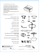
1. Unpacking Your Fan. Carefully open the packaging. Remove items from Styrofoam inserts. Remove motor housing and place on carpet or Styrofoam to avoid damage to finish. Do not discard fan carton or Styrofoam inserts should this fan need to be returned for repairs. Check against parts inventory that all parts have been included. 2. Parts Inventory. a b c a. hanging bracket. 1 piece b. 6 in. downrod and hanging ball. 1 piece c. canopy. 1 piece d e f d. yoke cover. 1 piece e. canopy cover.
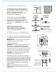
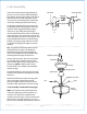
3. Installation Preparation. 12ft. - 20ft. (3.66m - 6.1m) blade edge 30 inches 7 feet (76cm) (2.13m) To prevent personal injury and damage, ensure that the hanging location allows the blades a clearance of 7ft. (2.13m) from the floor and 30in. (76cm) from any wall or obstruction. This fan is suitable for room sizes up to 400 square feet (37.2 square meters). 12ft. - 20ft. (3.66m - 6.1m) downrod installation This fan can be mounted with a downrod on a normal or vaulted ceiling.
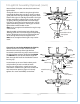
. Fan Assembly. If you wish to extend the hanging length of your fan, you must remove the hanging ball from the 6in. downrod provided to use with an extended downrod (sold separately). [If you wish to use the 6in. downrod, please proceed to instructions following the dotted line below.] set screw hole set screw stop pin hanging ball To remove hanging ball, loosen set screw on hanging ball, lower hanging ball and remove stop pin.
5. Fan Assembly. (cont.) With the hanging bracket secured to the outlet box and able to support the fan, you are now ready to hang your fan. Grab the fan firmly with two hands. Slide downrod through opening in hanging bracket and let hanging ball rest on the hanging bracket. Turn the hanging ball slot until it lines up with the hanging bracket tab. Tip: Seek the help of another person to hold the stepladder in place and to lift the fan up to you once you are set on the ladder.
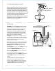
. Canopy Assembly. Locate 2 screws on underside of hanging bracket and remove screw closest to the open end of the hanging bracket. Partially loosen the other screw. Lift canopy to hanging bracket. Place rounded part of slotted hole in canopy over loosened screw in hanging bracket and push up. Twist canopy to lock. Re-insert screw that was removed and then tighten both screws securely.
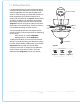
9. Switch Housing Assembly. Remove 1 screw from fitter plate on underside of motor and partially loosen the other 2 screws. Align slotted holes in center of switch housing with loosened screws in fitter plate, allowing male plug from motor housing to come through hole in middle of switch housing. Twist switch housing to lock. Re-insert screw that was removed and secure all screws.
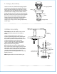
10. Light Kit Assembly (Optional). (cont.) Remove finial, finial plate and threaded washer from light kit fitter. Guide pull chain on switch housing through hole in top of light kit fitter, then raise glass shade in order to guide pull chains through corresponding holes at the bottom of the glass shade. Align threaded rod on light kit fitter with hole in middle of glass shade and push up gently, allowing threaded rod to come through hole.
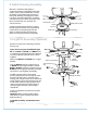
11. Testing Your Fan. It is recommended that you test fan before finalizing installation. Restore power from circuit box and light switch (if applicable). Test fan speeds with the pull chain on switch housing. Start at the OFF position (no blade movement). First pull will set the fan to HI. Second pull will set the fan to MEDIUM. Third pull will set the fan to LOW. Fourth pull will re-set the fan to OFF setting. Test light with pull chain in the middle.
Troubleshooting. Warranty. WARNING: Failure to disconnect power supply prior to troubleshooting any wiring issues may result in serious injury. LITEX LIMITED LIFETIME WARRANTY: LITEX INDUSTRIES, INC. warrants this fan to the original household purchaser for indoor use under the following provisions: 1- YEAR WARRANTY: LITEX INDUSTRIES, LTD. will replace or repair any fan which has faulty performance due to a defect in material or workmanship.
LEER ESTAS INSTRUCCIONES Y GUARDARLAS PARA UTILIZACION FUTURA El reglamento federal requiere que un ventilador de techo con juego de luz fabricado o importado después del 1ro de enero del 2009 limite el vatiaje total que consume el juego de luz a 190W. Por lo tanto, este ventilador tiene un aparato que sirve para limitar el vatiaje. . ly O . P .
SUGERENCIAS DE SEGURIDAD. ADVERTENCIA: Para evitar la posibilidad de una descarga eléctrica, desconectar la corriente en la caja de fusibles principal o el interruptor protector antes de iniciar la instalación del ventilador o antes de repararlo o instalar accesorios. 1. LEER TODAS LAS INSTRUCCIONES E INFORMACIÓN DE SEGURIDAD CUIDADOSAMENTE ANTES DE INSTALAR SU VENTILADOR Y GUARDAR ESTAS INSTRUCCIONES.
1. Desempaquetado del ventilador. Abrir el empaque cuidadosamente. Sacar los artículos del embalaje. Sacar el motor y ponerlo en una alfombra o en el embalaje para evitar rayar el acabado. Guardar la caja de cartón o el empaquetamiento original en caso de que tenga que mandar el ventilador para alguna reparación. Comprobar las piezas del ventilador con el inventario de piezas y verificar que se incluyeron todas. 2. Inventario de piezas. a. soporte de montaje. 1 unidad b a c b.
3. Preparación para la instalación. Para prevenir daño corporal y otros daños, estar seguro de que el lugar en donde va a colgar el ventilador le permite un espacio libre de 2,13m (7 pies) entre las puntas de las aspas y el piso y 76cm (30 pulg.) entre las aspas y cualquier pared u otra obstrucción. Este ventilador es adecuado para habitaciones hasta 37,2 metros cuadrados (400 pies cuadrados). Se puede colgar este ventilador con tubo en un techo regular o abovedado.
5. Ensamblaje del ventilador. Si usted desea extender la longitud colgante del ventilador, usted tendrá que quitar la bola que sirve tornillo de fijación para colgar del tubo de 15,24cm provisto para usarla con un tubo más largo (a la venta por separado). [Si desea utilizar el tubo de 15,24cm, favor de pasar a las instrucciones después de la línea punteada más abajo.
5. Ensamblaje del ventilador. (cont.) Ya que esté sujetado el soporte de montaje a la caja de salida y capaz de apoyar el ventilador, usted está listo para colgar el ventilador. Agarrar el ventilador firmemente con las dos manos. Deslizar el tubo por la abertura del soporte de montaje y dejar que se detenga la bola en el soporte. Girar la bola que sirve para colgar hasta que la ranura de la bola se alinee con la parte saliente del soporte de montaje.
7. Colocación de la cubierta decorativa. Localizar los 2 tornillos en la parte inferior del soporte de montaje y quitar el tornillo que está localizado más cerca del extremo abierto del soporte de montaje. Aflojar parcialmente el otro tornillo. Elevar la cubierta decorativa hasta el soporte de montaje. Poner la parte redondeada del agujero con ranura en la cubierta decorativa encima del tornillo aflojado en el soporte de montaje y empujar hacia arriba. Girar la cubierta decorativa para cerrarla.
9. Instalación de la caja de encendido. Quitar 1 tornillo de la placa de conexión en la parte inferior del motor y aflojar los otros 2 tornillos. Alinear los agujeros con ranura de en medio de la caja de encendido con los tornillos aflojados en la placa de conexión, dejando que el enchufe macho del bastidor del motor pase por el agujero de en medio de la caja de encendido. Girar la placa de la caja de encendido para cerrarla. Volver a introducir el tornillo que se quitó y asegurar todos los tornillos.
10. Instalación del juego de luz (opcional). (cont.) Quitar el adorno con rosca, la placa del adorno con rosca y la arandela con rosca del conectador para el juego de luz. Pasar la cadena de encendido en la caja de encendido por el agujero en la parte de arriba del conectador para el juego de luz. Subir la pantalla de vidrio para pasar las cadenas de encendido por los agujeros en la parte de abajo de la pantalla de vidrio.
11. Verificación del funcionamiento del ventilador. Se le recomienda poner el ventilador a prueba antes de terminar la instalación. Regresar la corriente de electricidad en el cortacircuitos y encender el interruptor de la luz en la pared (si se aplica). Verificar las velocidades del ventilador con la cadena de encendido en la caja de encendido. Empezar en estado de APAGADO (sin movimiento de las aspas). Con el primer tirón el ventilador estará en marcha ALTA.
Localización de fallas. Garantía. ADVERTENCIA: El no desconectar el suministro de fuerza eléctrica antes de hacer localización de fallas para cualquier problema de instalación eléctrica puede causar lesiones graves. GARANTIA LIMITADA DE POR VIDA DE LITEX: LITEX INDUSTRIES, LTD. garantiza este ventilador al comprador original de grupo familiar para uso interior con las siguientes condiciones: GARANTIA DE 1 AÑO: LITEX INDUSTRIES, LTD.