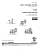
ITEM #0728855 WALL SCONCE FITTER MODEL #WS344-1BNK ITEM #0728848 #0728847 #0728846 VANITY BAR FITTER MODEL #VB344-2BNK #VB344-3BNK / #VB344-4BNK Français p. 9 Español p. 17 MODEL #WS344-1BNK MODEL #VB344-2BNK MODEL #VB344-4BNK MODEL #VB344-3BNK ATTACH YOUR RECEIPT HERE E342246 Purchase Date Questions, problems, missing parts? Before returning to your retailer, call our customer service department at 1-800-527-1292, 8:30 a.m. - 5 p.m., CST, Monday - Friday.
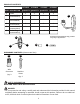
PACKAGE CONTENTS #0728855 PART DESCRIPTION A B C D E F Fixture Mounting Plate (preassembled) Mounting Screw (preassembled) Hex Nut (preassembled) Decorative Nut (preassembled) Socket Ring (preassembled) #0728848 #0728847 #0728846 QUANTITY QUANTITY QUANTITY QUANTITY 1 1 1 1 1 1 1 1 2 2 2 2 2 2 2 2 2 2 2 2 1 2 3 4 A Drawing representational only; product may vary in appearance. B D C E F HARDWARE CONTENTS (shown actual size) AA Wire Connector BB Machine Screw Qty. 3 Qty.
SAFETY INFORMATION • DO NOT connect this fixture to an electrical system that does not provide a means for equipment grounding. Never use a fixture in a two-wire system that is not grounded. Installing a fixture into an electrical system not having a proper grounding means could cause metal parts of the fixture to carry electrical currents if any of the fixture wires, wire connections or splices were to become broken, cut or loose during the mounting or normal operation of the fixture.
PREPARATION Before beginning assembly of product, make sure all parts are present. Compare parts with package contents list and hardware contents list. If any part is missing or damaged, do not attempt to assemble the product.
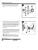
ASSEMBLY INSTRUCTIONS 3. Remove decorative nuts (E) from front of fixture (A) and remove mounting plate (B) from back of fixture (A). Save decorative nuts (E) for later use. 3 A B E E 4. Feed supply wires through center of mounting plate (B). Attach mounting plate (B) to outlet box (not included) using the existing washers and outlet box screws or the machine screws (BB).
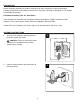
ASSEMBLY INSTRUCTIONS 5. Temporarily place fixture (A) over mounting plate (B) to determine amount of adjustment necessary for mounting screws (C). NOTE: The mounting screws (C) should come through holes in fixture (A) just enough so decorative nuts (E) will fit flush against fixture (A) when mounted. 5 Outlet Box A E B D Once mounting screws (C) are adjusted, use pliers (not included) to tighten hex nuts (D) on mounting screws (C) until hex nuts (D) touch mounting plate (B). C Set fixture (A) aside.
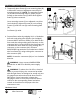
ASSEMBLY INSTRUCTIONS 7. Wrap electrical tape (not included) around each individual wire connector (AA) down to the wire. Push wire connectors (AA) gently back into outlet box. Carefully push excess wiring into outlet box. 7 A AA WARNING: Make sure no bare wire or wire strands are visible after making connections. AA 8. Align holes in fixture (A) with screws on mounting plate (B) and push fixture (A) toward wall.
ASSEMBLY INSTRUCTIONS 10. Install standard-base bulb(s) (not included). Use 60-watt max. incandescent bulb(s) or CFL/LED equivalent. WARNING: When replacing bulb(s), please allow bulb(s) and fixture to cool down before touching. 10 Bulb A Restore power and test fixture (A). If light does not function, please refer to TROUBLESHOOTING. CARE AND MAINTENANCE • Shut off main power supply. Wipe with soft cloth or use window cleaner. Do not use an abrasive cleaner.