LED IMPORTANT SAFETY INSTRUCTIONS Page 1 of 11 U351 Rev.
LED IMPORTANT SAFETY INSTRUCTIONS Page 2 of 11 U351 Rev.
LED IMPORTANT SAFETY INSTRUCTIONS CLX LED STRIP/LOW BAY INSTALLATION INSTRUCTIONS WARNING: Please read all “important safety instructions” prior to installation of this product.
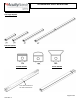
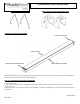
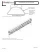
LED IMPORTANT SAFETY INSTRUCTIONS SECTION A: Identification of CLX Luminaire CLX Length Options CLX Lens Options PS1050 OPTION Sensor OPTION Test switch located on the side of the fixture Page 4 of 11 U351 Rev.
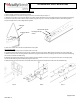
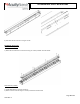
LED IMPORTANT SAFETY INSTRUCTIONS ZACVH V-HANGER ACCESSORY THCLX HANGER (SHIPS SCREW INSTALLED) SECTION B: HANDLING PRECAUTIONS PLASTIC LENS CAPS ACYRLIC LENS PLASTIC HOUSING END CAPS SHEET METAL HOUSING When handling the fixture during unpacking and installation take precautions of the plastic Lens and plastic end caps. Dropping the fixture or excess force on the end caps could cause damage. Section C: PRE-INSTALLATION FOR ALL MOUNTING 1) Ensure power is OFF.
LED IMPORTANT SAFETY INSTRUCTIONS SECTION D: INSTALLATION - SUSPENDED FIXTURE 1) Feed V-hanger into holes on the Driver channel 2) Ensure supply wire is not active. If using a continuous row mount skip to steps 5-9. 3) Remove access plate screw as shown below. Input wires will be attached to the access plate. Remove the necessary knockout(s) and connect input wires black to black, white to white and green to green. Use only UL listed connectors rated 75C or greater.
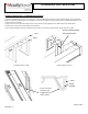
LED IMPORTANT SAFETY INSTRUCTIONS SECTION E: INSTALLATION – CLX HANGER MOUNT (THCLX) 1) Attach CLX brackets to structure. If mounting to a T-Grid snap Mounting bracket into T-Grid as shown below. Two CLX brackets MUST be used for standalone fixtures. If mounting in a continuous row one bracket per fixture with one additional bracket per row must be used at a minimum 2) Snap Fixture into the THCLX mounting bracket. Ensure fixture is fully engaged into the THCLX bracket, as shown below.
LED IMPORTANT SAFETY INSTRUCTIONS Section F: Wiring – Emergency (BGTD, PS1050) 1) Install fixture with Mounting brackets, directly to surface, or with V-hooks. Do not wire. 2) The emergency battery pack indicator light must be plugged in during installaion. Remove housing end cap near access plate as shown in previous instructions. 3) Fixture will be provided with a wiring harness at the access plate end.
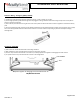
LED IMPORTANT SAFETY INSTRUCTIONS PRESS AGAINST LENS WALL TO DISENGAGE WDL DETACHMENT/REATTACHMENT PRESS TOWARD THE FIXTURE WHILE PRESSING AGAINST THE SIDE WALL TO REENGAGE. 5) To access electrical components, remove the six screws shown below. 6) Fixture will hang from wires with zip tie strain relief 7) LED Channel can hang from driver channel during servicing as shown below. Page 9 of 11 U351 Rev.
LED IMPORTANT SAFETY INSTRUCTIONS 8) Close LED channel and secure using six screws. SECTION H: Accessories Narrow Reflector (CLXRN) 1) Attach Narrow reflectors to LED channel using six screws provided. As shown below Wide Reflector (CLXRW) 1) Install Wide Reflector ontop of the fixture. 2) Attach to Driver Channel using four screws provided. As shown below. Page 10 of 11 U351 Rev.
LED IMPORTANT SAFETY INSTRUCTIONS Wireguard (WGCLX)/Louver (SBL) 1) Install accessory brackets to the top of the fixture with two screws provided. 2) Install Louver or Wireguard to Accessory bracket using two screws. Warranty terms are located at the link below: http://www.acuitybrands.com/resources/terms-and-conditions Page 11 of 11 U351 Rev.