
Specification Sheet

900 Northrop Road, Wallingford, CT 06492 • 1.800.PASSIVE • FX 203.269.9621 • www.sensorswitch.com
WARRANTY: Sensor Switch, Inc. warrants these products to be free of defects in manufacture and workmanship for a
period of 60 months. Sensor Switch, Inc., upon prompt notice of such defect, will, at its option, provide a Returned Material
Authorization number and repair or replace returned product.
LIMITATIONS AND EXCLUSIONS: This Warranty is in full lieu of all other representation and expressed and implied
warranties (including the implied warranties of merchantability and tness for use) and under no circumstances shall
Sensor Switch, Inc. be liable for any incidental or consequential property damages or losses.
TS-CMR-001A
Revised 06.16.10 © 2010 Sensor Switch
INSTALLATION
WIRING (DO NOT WIRE HOT)
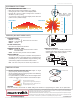
COVERAGE PATTERN
PROGRAMMING
Refer to instruction card IC7.001 for default settings and directions on programming the sensor via the push-button.
10 EXTENDED RANGE 360º LENS
0 ft
9
0 m
2.7
28 21 14 7 0 ft 7 14 21 28
8.5 6.4 4.3 2.1 0 m 2.1 4.3 6.4 8.5
SIDE VIEW
TOP VIEW
28
14
0 ft
14
28
8.5
4.3
0 m
4.3
8.5
• Best choice for large motion detection (e.g. walking)
• Viewing angle of 67º in a 360º conical shaped pattern
• Provides 28 ft (8.53 m) radial coverage when mounted to
standard 9 ft (2.74 m) ceiling
• 7 to 15 ft (2.13 to 4.57 m) mounting heights provide 16 to 36 ft
(4.88 to 10.97 m) radial coverage
Note: Sensor’s screw
axis is offset 7.5º from a
long detection segment
PUSH BUTTON
• Sensor’s mounting holes align with 3.5” octagon or single
gang handy box (screws not provided)
• Sensor will detect motions crossing segments more effectively
than motions parallel to beams
• For optimal detection, position sensor such that segments are
crossed upon entrance and unable to view outside the space
BLK
BLK
VIO (+)
WHT
GRY (-)
[D,ADC] Dimming Options
H
N
SWITCH
LOAD
N
N
LOAD
HOT
WHT
WHT
BLK BLK
BLK BLK
STANDARD WIRING
BLACK* - Line Input
BLACK* - Load Output
WHITE - Neutral
347 VAC OPTION (347)
Black wires are replaced w/ Red wires
DIMMING OPTIONS (D, ADC)
VIOLET - Connect to Violet control wire from 0-10 VDC
dimmable ballast
GRAY - Connect to Gray common wire from ballast
INITIAL POWER UP
The sensor’s relay is shipped in a latched closed position so
the lights will come on upon initial power-up. If the lights do not
immediately turn on (initial installation only) the latching relay
opened during shipment and will close within 30 secs.
Note: If the sensor loses power, the internal relay will latch to on.
SENSORS IN PARALLEL
Sensors may be wired in parallel; however, the
maximum load ratings stay the same. Do not wire
sensors with P or ADC option in parallel.
*BLACK wires can be reversed
}
*At 9ft Mtg.
A: When walking across beam,
detection will occur at approximately 28 feet (8.53
m).
B: When walking into beam, detection will occur
at approximately 24 feet (7.32 m).