
Installation Sheet


Page 2
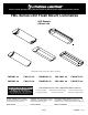
Figure 1
LISTE DES PIECES
``
LISTA DE EMBALAJE
REQUIRED TOOLS
HERRAMIENTAS REQUERIDAS
OUTILS REQUIS
INSTALLATION FIGURES FIGURES D’INSTALLATION FIGURAS DE LA INSTALACIÓN
1
FIXTURE PARTS LIST
Description Quantity
1) Housing .....................................1
2) Wireway Cover ..........................1
3) WireNuts* ...................................3
4) Diffuser ...................................... 1
5) Endcap ......................................2
* Contained in Parts Packs
Mounting Hardware Not Included
Descripción Cantidad
1) Carcasa ...................................... 1
2) Cubierta del canal de cable* ......1
3) Tuercas para cables* ..................3
4) Difusor ....................................... 1
5) Tapón ..........................................2
*Contenido en el Paquete de Piezas
Herraje para Montaje no esta Incluido
Description _Quantité
1) Boîtier.............................................1
2) Couvercle de la goulotte de guide-fils...1
3) Capuchons de connexion*..............3
4) Diffuseur..........................................1
5) Embouts.........................................2
*Compris dans les sacs d’emballag
Quincaillerie de Montage Inonnclus
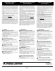
Figure 3Figure 2 Figure 4
INSTALLATION INSTRUCTIONS
Trouble Shooting Guide
If this fixture fails to operate properly, use the guide below to
diagnose and correct the problem.
Verify that fixture is wired properly.
Verify that fixture is grounded correctly.
The line voltage at the fixture is correct.
If further assistance is required, contact:
Technical Support at: (800) 748-5070
This LED light provides low maintenance service with no
bulbs to change.
Cleaning Diffuser: For best results, diffusers should be
washed with soap or mild detergent. Rinse with clear water
and allow to air dry.
This fixture is designed for indoor use ONLY and should
not be used in areas with limited ventilation or high
ambient temperatures.
FIXTURE MUST BE CONNECTED TO A NOMINAL
120 VOLT, 60 HZ POWER SOURCE. Any other
connection voids warranty.
This fixture is intended to be connected to a properly
installed and grounded UL listed junction box (
not
provided
) and should be installed according to the NEC
and local building codes.
Fixture must be secured to mounting surface with mounting
hardware appropriate to your application.
1. Remove fixture components and parts pack(s). Check
that all parts are included. See Page 2.
2. Remove the Wireway Cover (2) by compressing the
sides and dis-engaging from the Fixture Housing (1)
See Figure 1.
NOTE: TURN OFF POWER AT CIRCUIT BREAKER BOX !
Assistance may be required to support fixture during
installation.
3. With power turned off, lift Housing (1) to ceiling,
centering it over outlet box and parallel to walls. Mark
the location of the two 1/4” x 3/8” outer mounting slots.
Drill 1/8” pilot hole at each location.
If drill encounters ceiling joist, hold Housing (1) over
outlet box and pull supply wires into Housing through
the center hole. Use wood screw(s) (
not supplied
) to
secure Housing at each ceiling joist location.
See Figure 2 .
If drill does not encounter ceiling joist, enlarge hole(s) in
ceiling to accommodate a toggle nut(s) and bolt(s)
(
not supplied
). Pre-install the bolt(s) and nut(s) in
Housing. Lift Housing (1) over outlet box and pull supply
wires into the Housing through the center hole. Insert
toggle nut(s) in ceiling hole(s) and tighten toggle bolt(s).
See Figure 3.
4. Ground the fixture! Secure the green or bare copper
ground wire from the outlet box to the Green Ground
Wire from the Housing using Wire Nuts (3). If there is
no ground wire provided, consult your local electrical
code for approved grounding methods. See Figure 4.
5. Use Wire Nuts (3) to connect the white fixture wire to
the white power supply wire and the black fixture wire
to the black power supply wire. See Figure 4.
FOR PROPER CONNECTION, PLACE WIRENUT
OVER WIRES, TWIST CLOCKWISE UNTIL TIGHT.
NOTE: Make sure no wires are exposed.
6. Replace Wireway Cover (2) under tab(s) on one side of
fixture Housing (1) (
Make sure wires are not pinched
between Housing and wireway cover
) then compress
Cover to engage tab(s) on opposite side. Release and
confirm secure placement.
7. To install Diffuser (4), lift one side of diffuser almost to
ceiling and position one inside edge of Diffuser (4) over
side flange of Fixture Housing (1). Lift and shift opposite
side of Diffuser toward the Fixture Housing until Diffuser
rests on side flanges.
Page 3
Suggested Dimmers
This fixture is designed to operate with most standard Triac
Based (
Forward Phase-Control or Leading Edge)
dimmers
and is not compatible with 0-10v dimming systems.
Note: Below is a list of dimmers that have been tested with
this fixture. This list of dimmers does not imply any guar-
antee or warranty of compatibility with a particular applica-
tion. Dimmers that are not listed do not imply non-compat-
ibility.
Lutron: DV-603P, S-600-P
Leviton: 6633-PA
Pass & Seymour: HCL453PTCCCV6
Synergy: ISD 600 I 120
2
4
3
5
8. Turn on power at the circuit breaker box and verify
that fixture functions properly.