
Installation Sheet

REQUIRED TOOLS
HERRAMIENTAS REQUERIDAS
OUTILS REQUIS
INSTALLATION INSTRUCTIONS - ENGLISH
STEP-BY-STEP GUIDE
Page 5Page 4Page 2
GUÍA DE PASO-A-PASO
1. Remove fi xture components and parts pack(s). Check
that all parts are included. See Page 2.
2. Uninstall Decorative End Cap (2) and Diffuser (3) by un
screwing the Decorative Cap Nut (1) at each end of the fi xture.
Remove Ends and Diffuser and place to the side.
3. Squeeze Wireway Cover (5) above embossed tab area to
release from the Fixture Housing (6).
WARNING: Before wiring fi xture to the power supply, turn off
electricity at fuse or circuit breaker box!
Note: This fi xture is designed to be surface mounted on drywall or
inverted T-grid ceiling systems. Mounting hardware requirements
will depend on mounting method.
Assistance may be required to support fi xture during installa-
tion.
4. Lift fi xture housing to ceiling, center over outlet box and
parallel to walls. Mark ceiling with pencil for mounting holes
through (2) 1/4” x 3/8” outer mounting slots. Drill 1/8” pilot hole
at each location.
If drill encounters ceiling joist, hold Fixture Housing over outlet
box and pull supply wires into Housing through the center hole.
Use wood screw(s) (not supplied) to secure Housing at each
ceiling joist location. See Fig. 2.
If drill does not encounter ceiling joist, enlarge hole in ceil-
ing to accommodate toggle nut(s) and bolt(s) (not supplied).
Pre-install the bolt(s) and nut(s) in Fixture Housing. Lift Housing
over outlet box and pull supply wires into the Housing through the
center hole. Insert toggle nut(s) in ceiling hole(s) and tighten
toggle bolt(s). See Fig. 3.
5. Using Wirenuts (4) provided, connect supply (house) wires
to fi xture wires, white to white and black to black and green to
green or bare copper ground wire. See Fig. 4.
FOR PROPER CONNECTION, PLACE WIRENUT OVER WIRES,
TWIST CLOCKWISE UNTIL TIGHT. MAKE SURE NO WIRES
ARE EXPOSED
6. Replace Wireway Cover (5) under tab(s) on one side of
Fixture Housing (6) (
Make sure wires are not pinched
between Housing and wireway cover
) then compress
Cover to engage tab(s) on opposite side. Release and
confi rm secure placement.
7. Install Decorative End Cap (2) onto one end of the fi xture by
placing over exposed threaded nipple-secure with End Cap Nut
(1). See Fig. 5.
8. Slide Diffuser (3) between Decorative End Cap (2) and
Fixture Housing (6). See Fig. 6. While supporting Diffuser
install other Decorative End Cap and Nut. See Fig. 7.
9. Turn on electricity at fuse or circuit breaker box and verify that
fi xture functions properly.
Guía para la solución de problemas
Si la instalación no funciona adecuadamente, utilice la guía
que aparece a continuación para determinar cuál es el
problema y solucionarlo.
Verifi que que la instalación esté conectada correcta
mente.
Verifi que que la instalación esté conectada a tierra de
manera adecuada.
Que la línea de voltaje de la luminaria sea la correcta.
Si necesita obtener más ayuda, comuníquese con:
Soporte técnico al: (800) 748-5070
Esta luz de led proporciona un servicio de bajo manten-
imiento sin tener que cambiar bombillas.
Limpieza del difusor: Para obtener mejores resultados,
los difusores se deben lavar con jabón o detergente suave.
Enjuagar con agua limpia y dejar secar al aire.
Reductores de alumbrado recomendados
Este montaje se diseñó para operar con la mayoría de los
reductores de alumbrado con triac estándares (control de
fase directa o borde de ataque) y no es compatible con los
sistemas de reducción de luz de entre 0 y 10 V.
Nota: A continuación se enumera una serie de reductores
de alumbrado que han sido probados con este montaje.
Este listado de reductores de alumbrado no garantiza la
compatibilidad con ninguna aplicación en particular. Los
reductores de alumbrado que no se incluyen en la lista no
son necesariamente incompatibles.
Lutron: DV-603P, S-600-P
Leviton: 6633-PA
Pass & Seymour: HCL453PTCCCV6
Synergy: ISD 600 I 120
Esta instalación está diseñada SOLO para uso interior y
no se la debe utilizar en áreas con poca ventilación o alta
temperatura ambiente.
LA INSTALACIÓN DEBE ESTAR CONECTADA A UNA
FUENTE DE ENERGÍA NOMINAL DE 120 VOLTIOS, 60
HZ. Cualquier otro tipo de conexión anulará la garantía.
Esta instalación ha sido diseñada para conectarse a una
caja de unión aprobada por UL debidamente instalada
y puesta a tierra (no suministrada), y debe ser instalada
de acuerdo con el Código Eléctrico Nacional (NEC) y los
códigos de edifi cación locales.
La instalación debe asegurarse a la superfi cie de montaje
mediante los componentes de montaje adecuados para su
aplicación.
1. Retire los componentes del montaje y los paquetes con las
piezas. Verifi que que todas las piezas estén incluidas. Con
sulte la página 2.
2. Desinstale el cabezal decorativo (2) y el difusor (3) al de
senroscar la tuerca del cabezal decorativo (1) en cada ex
tremo del montaje. Retire los extremos y el difusor, y colóque
los a un lado.
3. Apriete la cubierta del canal de cable (5) por encima del
área de la lengüeta grabada para sacarla de la carcasa de
instalación (6).
ADVERTENCIA: ¡Antes de conectar el montaje a la fuente de
energía, desactive la electricidad desde la caja de fusibles o el
disyuntor!
Nota: Este montaje está diseñado para ser montado sobre la
superfi cie de láminas de yeso o en sistemas de techos de rejillas
T invertidos. Los requerimientos de los componentes de montaje
dependerán del método de montaje.
Puede que necesite ayuda para sostener el montaje durante
la instalación.
4. Levante la carcasa de instalación hacia el techo, y coloque
en el centro con respecto a la caja de salida y en forma
paralela a las paredes. Marque en el techo y con lápiz, los
orifi cios de montaje mediante (2) ranuras de montaje externo
de 1/4” x 3/8”. Perfore un orifi cio piloto de 1/8” en cada lugar.
Si al perforar se encuentra con una vigueta de techo,
mantenga la carcasa de instalación sobre la caja de salida
y pase los cables de suministro a la carcasa a través del
orifi cio central. Utilice tornillos de madera (no proporcionados)
para asegurar la carcasa en cada ubicación de la vigueta del
techo. Consulte la Fig. 2.
Si al perforar no se encuentra con una vigueta del techo,
agrande los orifi cios en el techo para colocar las tuercas y pernos
acodados (no incluidos). Preinstale los pernos y las tuercas en
la carcasa de instalación. Levante la carcasa sobre la caja de
salida y pase los cables de suministro a la carcasa a través del
orifi cio central. Inserte las tuercas acodadas en los orifi cios del
techo y ajuste los pernos acodados. Consulte la Fig. 3.
5. Con las tuercas para cables provistas (4), conecte los cables
de suministro a los cables de montaje: de blanco a blanco, de
negro a negro y de verde a verde o a cable conductor de tierra
de cobre sin recubrimiento. Consulte la Fig. 4.
PARA UNA CONEXIÓN APROPIADA, COLOQUE LA TUERCA
PARA CABLES SOBRE ESTOS Y GIRE HACIA LA DERECHA
HASTA AJUSTAR. ASEGÚRESE DE QUE NO QUEDEN
CABLES DESCUBIERTOS.
6. Vuelva a colocar la cubierta del canal del cable (5) bajo las
lengüetas en un lateral de la carcasa de instalación (6)
(asegúrese de que los cables no queden presionados entre
la carcasa y la cubierta del canal del cable) y luego presione la
cubierta para encajar las lengüetas en el lateral opuesto.
Suelte y confi rme que esté fi rmemente colocada.
7. Instale el cabezal decorativo (2) en un extremo del montaje
mediante la colocación de boquillas roscadas expuestas
y asegure la tuerca del cabezal decorativo (1). Consulte
la Fig. 5.
8. Deslice el difusor (3) entre el cabezal decorativo (2) y
la carcasa de instalación (6). Consulte la Fig. 6.
Figure 7
Figure 6
Figure 5
Mientras sostiene el difusor, instale el otro cabezal y tuerca
decorativos. Consulte la Fig. 7.
9. Active la electricidad en la caja de fusibles o el disyuntor,
y verifi que que la instalación funcione correctamente.
LISTE DES PIÈCES DU LUMINAIRE
LISTA DE PIEZAS DEL MONTAJE:
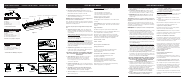
FIXTURE PARTS LIST
INSTALLATION FIGURES
FIGURES D’INSTALLATION
FIGURAS DE LA INSTALACIÓN
Trouble Shooting Guide
If this fi xture fails to operate properly, use the guide below to
diagnose and correct the problem.
Verify that fi xture is wired properly.
Verify that fi xture is grounded correctly.
The line voltage at the fi xture is correct.
If further assistance is required, contact:
Technical Support at: (800) 748-5070
This LED light provides low maintenance service with no bulbs
to change.
Cleaning Diffuser: For best results, diffusers should be washed
with soap or mild detergent. Rinse with clear water and allow
to air dry.
Suggested Dimmers
This fi xture is designed to operate with most standard Triac
Based (
Forward Phase-Control or Leading Edge)
dimmers and
is not compatible with 0-10v dimming systems.
Note: Below is a list of dimmers that have been tested with
this fi xture. This list of dimmers does not imply any guarantee
or warranty of compatibility with a particular application. Dim-
mers that are not listed do not imply non-compatibility.
Lutron: DV-603P, S-600-P
Leviton: 6633-PA
Pass & Seymour: HCL453PTCCCV6
Synergy: ISD 600 I 120
This fi xture is designed for indoor use ONLY and should
not be used in areas with limited ventilation or high
ambient temperatures.
FIXTURE MUST BE CONNECTED TO A NOMINAL
120 VOLT, 60 HZ POWER SOURCE. Any other
connection voids warranty.
This fi xture is intended to be connected to a properly
installed and grounded UL listed junction box (
not
provided
) and should be installed according to the NEC
and local building codes.
Fixture must be secured to mounting surface with mounting
hardware appropriate to your application.
Description Quantity
1) End Cap Nut ...............................2
2) Decorative End Cap ..................2
3) Diffuser .......................................1
4) *Wirenuts ...................................3
5) Wire Way Cover .........................1
6) Fixture Housing .........................1
* Contained in Parts Packs
Figure 2 Figure 3 Figure 4
Figure 1
1) End Cap Nut
2) Decorative End Cap
3) Diffuser
4) Wirenuts
5) Wire Way Cover
6) Fixture Housing
Description Quantity
1) Tuerca del cabezal decorativo .....2
2) Cabezal decorativo ......................2
3) Difusor .........................................1
4) Tuercas para cables ....................3
5) Cubierta del canal del cable ........1
6) Carcasa de la instalación ............1
*Incluidos en los paquetes de piezas
Description Quantity
1) Écrou d’embout ..........................2
2) Embout décoratif ........................2
3) Diffuseur ....................................1
4) *Capuchons de connexion ........3
5) Couvercle du chemin de câbles 1
6) Boîtier du luminaire ...................1
*Contenu dans les emballages des pièces