LED IMPORTANT SAFETY INSTRUCTIONS U02301 Rev.
LED IMPORTANT SAFETY INSTRUCTIONS U02301 Rev.
LED IMPORTANT SAFETY INSTRUCTIONS IBG LED HIGHBAY INSTALLATION INSTRUCTIONS WARNING: Please read all “important safety instructions” prior to installation of this product.
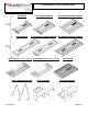
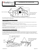
LED IMPORTANT SAFETY INSTRUCTIONS SECTION A: Identification of IBG Luminaire IBG 8000LM IBG 12000LM, 15000LM IBG 18000LM, 24000LM, 30000LM 2FT IBGN 18000LM IBGN 24000LM, 30000LM, 36000LM IBG 36000LM, 48000LM, 60000LM 4FT BPK OPTION (Access Plate not removable) HBBS V-HANGER ACCESSORY U02301 Rev.
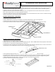
LED IMPORTANT SAFETY INSTRUCTIONS SECTION B: REQUIRED HANDLING LOCATIONS BAD FOR HANDLING GOOD FOR HANDLING VENT HOLES, DO NOT PUT SPLICE CONNECTIONS ABOVE VENT HOLES When handling the fixture during unpacking and installation do NOT use LED Modules for carrying/support. DO use the center channel and end caps for carrying/support Section C: PRE-INSTALLATION FOR ALL MOUNTING 1) Ensure power is OFF. 2) Inspect the mounting location for damage before installing new IBG Luminaire.
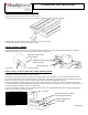
LED IMPORTANT SAFETY INSTRUCTIONS 3) Remove access plate screw as shown above. Input wires will be attached to the access plate. Remove the necessary knockout(s) and connect input wires black to black, white to white and green to green. Use only UL listed connectors rated 90C or greater. Purple and Gray wires are low voltage dimming leads. 4) Make any necessary electrical connections. Supply wire must meet applicable electrical codes and be rated for a minimum of 90⁰C.
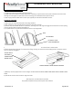
LED IMPORTANT SAFETY INSTRUCTIONS Section G: Installation – External Occupancy Sensor 1) External Occupancy sensor will be pre-wired to the fixture. 2) Install external occupancy sensor to fixture by snapping into end cap as shown in the fixture below. 3) Rotate/Align the sensor head such that the sensor lens is parallel to the floor. 4) Install fixture based on specified mounting instructions. Section H: Installation – NPP16D 1) NPP16D will be prewired to the fixture and attached to the access plate.
LED IMPORTANT SAFETY INSTRUCTIONS Section J: Wiring – IMP Connector 1) Install fixture based on specified mounting instructions. 2) A 5/8” knock out is located on the IMP access plate. If dimming is required remove access plate and knock out knockout. Pull dimming wires through access plate and connect to dimming circuit. Reattached access plate to fixture. 3) Snap supply power with IMP male connector (not supplied) into luminaire female IMP connector. SECTION K: SERVICING 1) Clean fixture as needed.