
Instructions / Assembly

INSTALLATION
Rigid Pendant Mount ("PM" mounting option):
1. Disconnect power.
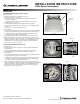
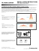
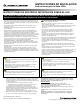
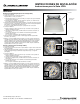
2. Install the accessory reflector to the fixture (see Figure 1).
Tighten screws 3-5 in-lbs. (.35-.56 N-m).
a. For acrylic reflectors use the three screws and holding brackets installed in
the fixture. (see Figure 2).
b. For aluminum reflectors remove the holding brackets and use only the three
provided screws (see Figure 3).
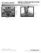
3. Open the wiring door on the J-Box atop the fixture and mount the fixture to
3/4" conduit/pipe through the hub in the J-Box (see Figure 4). Conduit/pipe supplied
by others.
a. Lock in place using lock nut supplied with fixture.
4. Connect Wiring.
a. Check line voltage and make sure it matches the fixture input voltage requirements.
b. Follow all the local and NEC codes while making connection to AC power source.
c. If dimming required, use the provided dimming leads (Dim+ and Dim- leads).
If dimming is not required, cap off any unused leads.
5. Close wiring door using provided screw. Tighten screw 8-10 in-lbs.(.90-1.13 N-m).
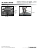
6. Balance the fixture by loosening the two screws on the top hub (see Figure 4) and
sliding the hub. Tighten screws after balancing. If not enough movement is achieved with
the top hub to balance the fixture, the J-Box can also provide additional travel by
loosening the four screws at the J-Box base. Tighten all screws after balancing.
Tighten screws 8-10 in-lbs. (.90-1.13 N-m).
Hook and Cord ("6CH" mounting option):
1. Disconnect power.
2. Install the accessory reflector as explained in step 2 of the Rigid Pendant Mount
instructions above.
3. Using the provided hook, hang the fixture from eyebolt or any other hanging
arrangement. Bottom out the locking screw on the hook (see Figure 5).
4. Connect Wiring.
a. Check line voltage and make sure it matches the fixture input voltage requirements.
b. Using the provided cord, connect to the AC supply.
c. Follow all the local and NEC codes while making connection to AC power source.
d. If dimming is required, use the provided dimming leads (Dim+ and Dim- leads).
If dimming is not required, cap off any unused leads.
5. Balance the fixture by loosening the two screws on the top hub (see Figure 4) and
sliding the hub. Tighten screws after balancing. If not enough movement is achieved with
the top hub to balance the fixture, the J-Box can also provide additional travel by
loosening the four screws at the J-Box base. Tighten all screws after balancing.
Tighten screws 8-10 in-lbs. (.90-1.13 N-m).
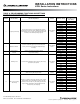
INSTALLATION INSTRUCTIONS
JCBL Series Instructions
Fixture
Bracket
Screw
Accessory
Reflector
Figure 1
Figure 2
Keyhole
Screw
Figure 3
©2016 Acuity Brands Lighting, Inc. Rev 4/16 P4130 pg 2 of 7
One Lithonia Way, Conyers, GA 30012
Phone: 800-315-4963 Fax: 770-929-8789 www.lithonia.com