
Installation Guide


INSTALLATION
INSTRUCTIONS
LITHONIA TRACK LINE VOLTAGE FIXTURES
DOWNLIGHTING
& TRACK
SYSTEMS
ONE LITHONIA WAY,
CONYERS,
GEORGIA 30012,
TELEPHONE 770-922-9000,
FAX
770-860-3106
www.lithonia.com
IN CANADA: 1100 50TH AVE., LACHINE, QUEBEC H8T
2V3
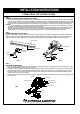
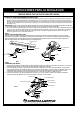
FIELD CUTTING TRACK TO SPECIAL LENGTHS (OPTIONAL):
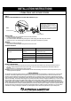
IF ADDITIONAL MOUNTING HOLES ARE NEEDED (OPTIONAL):
1. Locate desired mounting hole(s) on the inside of the track section along the center line.
2. Using 3/16th diameter drill bit, drill a hole through the track channel.
Note: Cutting should be done preferably from the dead end of the track.
1. Remove dead end fitting and pull copper bus bars and insulators flush or even with one end of the track.
2. With a hacksaw, cut the flush end (the side with insulators and bus bars even to end) to desired length. Be sure to allow 1/8th in. For
dead end fitting which must be reinstalled to the track end.
3. Remove all burrs from the track, insulators and copper bus bars.
4. Push copper bus bars back into the insulators 3/8th in. from the end of the insulators.
CAUTION:
Note: After you complete step 4, bus bar insulators should be a minimum of 3/8th in. and a maximum of 1/2 in. from each end of the insulator
If this is not the case, make appropriate modifications.
5. Reinstall the dead end and/or appropriate feed connector and tighten the screw.
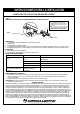
After track has been field cut, make certain that each length of track that is 4 feet (1.22m) or less in length has one mounting opening
spaced a maximum of 6 in. (150mm) from each track end section. A single section of track that is greater than 4 feet (1.22m) in length must
have mounting openings a maximum of 12 in. (300mm) from each end of the track with additional openings a minimum of every 4 feet (1.22m)
long the length of the track section. Additional openings every 4 feet (1.22m) along the track section may be added as needed.
CAUTION:
Take care that you do not damage the bus bar insulators during the drilling operation. If you accidentally damage any insulators,
discard the track section. To prevent the risk of fire, or injury to person(s). DO NOT ATTEMPT TO USE IT IN THE INSULATION.
3. Remove all burrs and install track as described above.
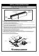
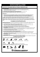
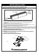
INSTALLATION INSTRUCTIONS (AS SHOWN IN DIAGRAM):
OUTLET BOX
TOGGLEBOLT
CEILING
WIRE CONNECTOR
BLACK (HOT WIRE)
END CAP
KEYHOLE SLOT
TRACK
MOUNTING SCREW
WHITE
NEUTRAL WIRE
GREEN
GROUND WIRE
PLASTIC CANOPY
DEAD END
FITTING TO
REMOVE. LOOSEN
SCREW AND SLIDE
FITTING OUT.
REDRILL
MOUNTING
HOLE(S) IF
NECESSARY
NEW CUT MUST BE AT AN
EXACT RIGHT ANGLE (90°)
FIG. 1