
Installation Guide


INSTALLATION
INSTRUCTIONS
LITHONIA TRACK LINE VOLTAGE FIXTURES
DOWNLIGHTING
& TRACK
SYSTEMS
ONE LITHONIA WAY,
CONYERS,
GEORGIA 30012,
TELEPHONE 770-922-9000,
FAX
770-860-3106
www.lithonia.com
IN CANADA: 1100 50TH AVE., LACHINE, QUEBEC H8T
2V3
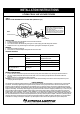
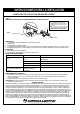
STEP 3:
ELECTRICAL CONNECTIONS:
1. When removing the supply wires from the ceiling outlet box the white supply and green (or bare copper) ground wire should be on one side
of the track and the black supply wire should be on the other.
2. Connect the white wire (neutral or common) from the supply circuit to the white from the floating live-end connector. Connect the black (hot)
wire from the supply circuit to the black wire from the floating live-end connector. Connect the green or bare copper ground wire from the
supply circuit to the green conductor of the floating live-end connector. Secure splices with UL Listed wire connectors suitable for the size,
type and number of conductors. (see Figure4)
3. Carefully push the leads into the ceiling outlet box. Tighten the toggle bolts and attach the plastic floating live-end connector canopy with the
screws provided.
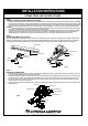
STEP 2:
ATTACH MOUNTING PLATE TO TRACK:
Place the mounting plate on the back side of the track section so that the set screws on plate fit over the ridges on both sides of the track. This
will insure grounding continuity. Center the plate with previously installed floating live-end connector and tighten the set screws on both sides
of the track. Pass wires from the floating live end connector through the hole in the mounting plate into ceiling outlet box. (See Figure 3)
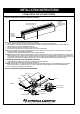
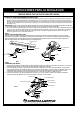
STEP 1:
CONNECT FLOATING LIVE-END CONNECTOR TO TRACK:
1. The track section and floating live-end connector must be assembled so that polarity between conductors is maintained. NOTE: The floating
live-end connector has a tab on one side and the track has an indentation which runs the length of the track channel (Refer to Figure2). Align
the floating live-end connector tab with the track indentation and insert the floating live-end connector into the track channel so that the base
of connector fits flush against the track twist connector clockwise 1/4 (one quarter) turn so that the connector fits snugly against the track.
CAUTION:
When the floating live-end connector is twisted into position make certain that the two copper tabs at the base of the connector align
with the two copper bars inside the track-this is necessary to maintain polarity.
2. The floating live-end connector should be positioned along the track so that it will alignwith the outlet box after track is installed. The plastic
canopy must enclose the floating live-end connector and cover the outlet box. The plastic canopy should not cover the track mounting
attachment holes. The plastic canopy attaches to the mounting plate with the 2 screws after Electrical connections are made.
BLACK
GROUND
WHITE
TAB
FLOATING LIVE-END
CONNECTOR
INDENTATION
TRACK SECTION
MOUNTING PLATE
SCREW
WHITE
GREEN
BLACK
WIRE CONNECTOR
WHITE (NEUTRAL)
OUTLET BOX
BLACK (HOT)
GREEN (GROUND)
WHITE
BLACK
GREEN
FIG. 2
FIG. 3
FIG. 4
MOUNTING PLATE