
Installation Guide


Description Quantity
1) Housing Assembly ............................ 1
2) Wireway Cover Assembly .................. 1
2) Wireway Cover Assembly (L96 2LL) .. 2
3) Wirenuts* .......................................... 3
4) LED Driver ......................................... 1
5) Alignment Bracket- 2LL only .............. 1
6) Bracket Screw- 2LL only .................... 2
*Contained in Part Packs
FIXTURE PACKING LIST
INSTALLATION INSTRUCTIONS - ENGLISH
STEP-BY-STEP GUIDE
Page 5Page 4Page 2
GUÍA DE PASO-A-PASO
INSTALLATION FIGURES
FIGURES D’INSTALLATION
FIGURAS DE LA INSTALACIÓN
Description Quantité
1) Bloc boîtier ........................................ 1
2) Couvercle .......................................... 1
2) Couvercle (L96 2LL) .......................... 2
3) Capuchons de connexion* ................. 3
4) Conducteur DEL ................................ 1
5) Support d’alignement 2LL seulement 1
6) Vis de support 2LL seulement ........... 2
*Compris dans les sacs d’emballage
LISTE DES PIECES
Descripción Cantidad
1) Ensamblaje de la Carcasa ............... 1
2) Cubierta ........................................... 1
2) Cubierta (L96 2LL) ........................... 2
3) Capuchones de Alambre* ................ 3
4) Controlador de led ............................ 1
5) Ménsula de alineación:
2LL únicamente ................................ 1
6) Tornillo de ménsula:
2LL únicamente ................................ 2
* Contenido en el Paquete de Piezas
LISTA DE EMBALAJE
REQUIRED TOOLS
HERRAMIENTAS REQUERIDAS
OUTILS REQUIS
2
1
4
5
6
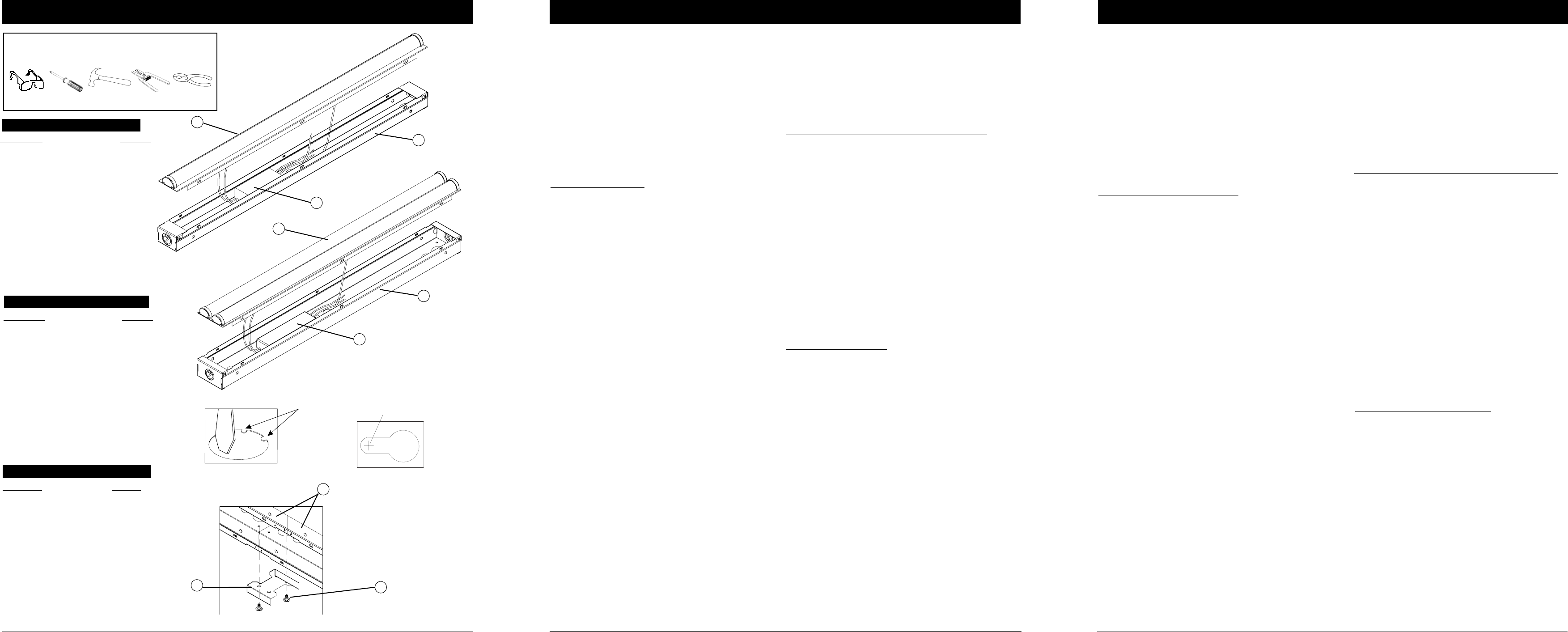
Figure 1
1. Remove fixture components and parts pack(s).
Check that all parts are included. See Fig. 1.
Note: Turn off power at circuit breaker box!
2. Remove Wireway Cover (2) by lifting upward on ex-
posed edges of part. Start in the middle and work
outward.
3. Determine appropriate knockout on Housing
assembly (1) for removal in relationship to incoming
power supply. (Knockouts are located on each end
and back of the fixture.)
To remove knockouts:
Place standard screwdriver on edge of circle (on opposite
side from retaining tabs) and gently strike with hammer.
Grip edge with pliers and flex back and forth until removed.
See Fig. 2.
4. If using romex strain relief bushing, install the
bushing into the open hole.
5. Insert house power supply cable through open hole
or strain relief bushing.
6. Position the Fixture Housing (1) against the mount-
ing surface and with a pencil, mark the screw hole
locations to be located at the narrow section of the key-
holes. See Fig. 3.
7. Using a drill with a 1/16” drill bit, make two small
pilot holes at the marked screw hole locations. If drill bit
does not encounter a stud or wood surface, use toggle
bolts or suitable fastener depending on structural
conditions. If drill bit does encounter wood surface, use
#10 wood screw.
8. Partially install the Mounting Screws. Position the
Fixture Housing against the mounting surface with the
screw heads through the keyhole mounting holes.
Slide the fixture until the screw heads are through the
narrow section of the key holes. Finish tightening the
screws to secure the fixture against the mounting
surface.
For Continuous Row installation (2LL versions only)
9. Remove endplate from Housing assembly (1) to
install alignment bracket.
10. With fixtures installed end to end- install
bracket (5) with two screws (6) provided. One
screw per fixture as noted in Fig. 4.
WIRING AND FIXTURE OPERATION CAUTION:
Connect fixture to supply wires rated for at least
90°C (194°F).
Do not use fixture on dimming circuits.
11. Cut supply cable to desired length. Strip black
and white wire leads with wire strippers to expose
3/8”-7/16” of bare metal.
12. Using Wirenuts (3) provided, connect supply
(house) wires to fixture wires - white to white, black
to black, and green to green or bare copper ground
wire.
13. Bundle wires in tight grouping to be out of the
way and reinstall Wireway Cover assembly (2)
Trouble Shooting Guide
If this fixture fails to operate properly, use the guide
below to diagnose and correct the problem.
Verify that fixture is wired properly.
Verify that fixture is grounded correctly.
The line voltage at the fixture is correct.
If further assistance is required, contact:
Technical Support at: (800) 315-4963
Accesorio de la ménsula de alineación para in-
stalación en fila continua- (versiones 2LL única-
mente)
9. Retire la placa para extremo del montaje para
instalar una ménsula de alineación.
10. Con los montajes instalados de extremo a ex-
tremo, instale la ménsula con los dos tornillos que se
proporcionan; un tornillo por montaje, como se indica
en la Fig. 4.
CUIDADO DEl ALAMBRADO Y OPERACION DEL
LUMINARIO:
Conecte luminario a alambres de suministro de
electricidad clasificados a por lo menos 90°C
(194°F). No use el luminario en circuitos con at-
enuador de intensidad.
11. Corte el cable de suministro a la longitud
deseada. Pele el alambre blanco y negro con un
pelacable hasta exponer 3/8”-7/16” de metal
descubierto.
12. Usando los capuchones de Alambres
suministrados, conecte los cable se suministro
(de la casa) a los cables del luminario, blanco con
blanco, negro con negro y, verde con verde o,
cobre desnudo a cable de tierra.
13. Agrupe los alambres bien apretados para que
estén fuera del medio y vuelva a instalar la
cubierta del canal del alambrado.
Guía de Localización de Averías
Si este luminario falla de operar apropiadamente,
use la siguiente guía para diagnosticar y corregir el
problema.
Verifique que el luminario este alambrado
apropiadamente.
Verifique que el luminario este conectado tierra
correctamente.
El voltaje de la línea en el luminario este correcto
Si requere ayuda adicional, contacte:
Technical Support al:
(800) 315-4963
1. Saque los componentes del luminario y paquete(s) de
piezas. Compruebe que todas las piezas estén
incluidas. Vea Fig. 1.
Nota: ¡Apague la electricidad en la caja de cortacircuitos!
2. Quite la cubierta del canal del alambrado
levantándola hacia arriba las orillas expuestas de la
pieza. Empiece en el centro y trabaje hacia afuera.
3. Determine el “knockout” apropiado para quitar en la
relación a los alambres entrantes de suministro de
electricidad. (Los “knockouts” estan localizados en cada
extremo en parte trasera del luminario).
Para remover knockout de metal:
Coloque un destornillador estándar en el extremo del
círculo (lado opuesto de las lengüetas de retención) y
suavemente golpee con el martillo. Sujete un extremo con
las pinzas y flexione hacia atrás y adelante hasta que se
desprenda. Vea Fig. 2.
4. Si esta utilizando un buje de alivio de tensión romex,
cierre de golpe el buje en el agujero libre.
5. Meta el alambre de suministro de electricidad de la
casa a través del agujero abierto o el buje de alivio de
tensión.
6. Coloque la caja de la luminaria contra la superficie
de montaje y con un lápiz, marque las localizaciones de
los agujeros para los tornillos que serán ubicados en la
sección angosta de los “keyholes”. Vea Fig. 3.
7. Usando un taladro con una broca de 1/16”, haga dos
pequeños agujeros pilotos en las ubicaciones marcadas
para agujeros de tornillos. Si la broca del taladro no se
encuentra con un machón o madera, use perno de
expansión u otro sujetador conveniente dependiendo de
condiciones estructurales. Si la broca se encuentra con
una superficie de madera, use tornillo de madera #10.
8. Instale parcialmente los tornillos de montaje.
Coloque la carcasa del luminario contra la superficie de
montaje con las cabezas de los tornillos a través de los
agujeros de montaje del “keyhole”. Deslice el luminario
hasta que las cabezas de los tornillos estén en la
sección estrecha de los “keyholes”. Termine apretando
los tornillos para asegurar el luminario contra la
superficie de montaje.
1
2
1
4
Figure 4
Figure 2
Screw Hole Location
Figure 3
Retaining Tabs