
Installation Guide


page 3
INSTALLATION INSTRUCTIONS
Upon receipt of fi xture, thoroughly inspect for any freight damage.
All damage should be reported to the delivery carrier. Compare
the catalog description listed on the packing slip with the fi xture
label on the inside of the housing to be sure you have received
the correct merchandise. Note: Account for small parts and
destroy packing material, as these may be hazardous to children.
Turn OFF Power at circuit breaker box.
CAUTION: Do not rely on wall switch alone to turn off power.
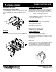
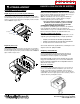
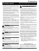
OFL2 IS - Integral Slipfi tter Mounting:
Required Tools: 1/4” and 3/16” hex socket driver and fl at head
screwdriver.
Remove the cover plate to access the integral wiring compartment
using a fl at head screwdriver or 1/4” hex socket driver. Place
integral slipfi tter onto 2-3/8” diameter Tenon ensuring that the
wires are pulled through the integral wiring compartment without
pinching. Secure slipfi tter to the Tenon by tightening the 3/8” hex
socket set screws using a 3/16 hex socket driver. Make supply
connections through the integral wiring compartment. Refer to
wiring instructions on next page for power connection. Push wires
into compartment and re-install cover plate. To adjust the tilt angle
of the fi xture, loosen the 1/4” hex socket screw above the integral
wiring compartment. Rotate fi xture to desired angle and re-tighten
center screw.
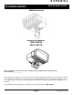
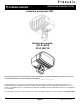
OFL1&2 YK - Yoke Mounting:
Required Tools: Hex socket driver and regular screwdriver.
To adjust the tilt angel of the fi xture, loosen but do not remove
the 3/8” hex bolts on both sides of the yoke. While holding weight
of fi xture, remove 10-32” set screw, adjust to desired angle and
reinstall set screw in appropriate matching hole. Re-ighten hex
bolts to secure.
Mount fi xture to the desired bracketry using the hole pattern
provided on the yoke bracket (see template below) with a 5/8” bolt
(if center hole is used) or 1/2” bolts (if outer holes are used), lock
washer, and nut (not provided). Tighten to 30ft-lbs.
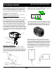
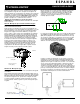
The Yoke Mounting option is provided with 16AWG power supply
cord. The power supply cord has 0.4 inch outside diameter (O.D.).
A UL LISTED water tight cord connector suitable for use on 0.4
inch diameter size wet location fl exible cord shall be required in
order to install onto an outdoor junction box. See image below.
When installing onto an outdoor junction box and in order to
reduce risk of water entry, ensure that a Tefl on tape or silicone
sealant is applied on the threaded portion of the fi tting when being
installed. It is recommended that the water tight cord connector
be installed so that power supply cord exits towards the ground.
If existing wiring does not allow for installation of wires exiting
towards the ground, the use of an elbow suitable for wet location
use is recommended so that cord can exit towards the ground.
See images below. Refer to wiring instructions on next page for
power connection.
3/8” Hex bolt (2
plcs) use 9/16
socket driver
10-32” set screw
OLF2 IS
cover plate
1/4” hex socket screw
3/8” hex socket set
screws (4plcs)