
Installation Guide


page 3
INSTALLATION INSTRUCTIONS
WALL MOUNT (THROUGH WIRING)
Follow steps 1 to 3.
4B. Fasten wiring box to mounting surface and install conduit
Note: Mounting hardware and conduit not included.
Follow wiring instructions outlined in step 5 & 6.
7B. Push Wire Connectors into junction box. Align the fi xture
against the wiring box and tighten the Socket Set Screws to
secure fi xture in place.
Make sure all wiring access holes are sealed with weatherproof
silicone sealant (not included).
If desired place
photocell cap over
photocell to turn
off photocell function.
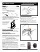
1. Remove fi xture components and parts pack. Check to
ensure all parts are included. Note: Account for small parts and
destroy packing material, as these may be hazardous to children.
2. Turn OFF Power at circuit breaker box.
CAUTION: Do not rely on wall switch alone to turn off power.
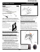
3. Use a 3/16” Allen Wrench
to loosen the two Socket
Set Screws on the rear of
the Fixture and remove
the Mounting Plate.
WALL MOUNT TO JUNCTION BOX
4. Fasten the Mounting Plate to the Junction Box. Use the
integrated bubble level to ensure that the Plate is level. Note:
Mounting screws not included.
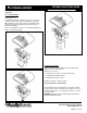
CAUTION: WIRING AND FIXTURE OPERATION
Make sure power is turned off.
5. To Ground fi xture use Wire Nut (6) to connect the (copper)
house supply ground wire & the (green) fi xture ground wire. Note:
If house wiring does not include a ground wire, consult your local
electrical code for approved grounding methods.
For proper connection, place wire nut over
wires and twist clockwise until tight.
6. To connect supply wires use Wire Nuts (6) to connect the
black fi xture wire to the black power supply wire and the white
fi xture wire to the white (neutral) supply wire.
7. Push Wire Connectors into junction box. Align the fi xture
against the mounting plate and re-tighten the Set Screws to
secure the fi xture in place. Note: Take care not to pinch the
power wires.
For Wet Location compliance, fi xture must be properly
sealed! For moisture seal, apply silicone caulking between the
mounting surface and Housing back as well as around sides of
Housing.
8. Turn on electricity at fuse or circuit breaker box and verify
success of installation.
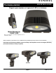
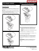
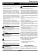
1) LED Light Fixture
3) Mounting Plate
4) 3/4” Screws
6) Wire Nuts
5) Wiring box
FIXTURE PACKING LIST
Description Quantity
1) LED Light Fixture................................................................. 1
2) Socket Set Screw ................................................................ 2
3) Mounting Plate .................................................................... 1
4) 3/4” Screw* .......................................................................... 2
5) Wiring box* .......................................................................... 1
6) Photocell Cap*..................................................................... 1
*Contained in parts packs
Mounting Hardware and
Silicone Sealant Required
REQUIRED TOOLS:
2) Socket Set Screws
Figure B
Figure A
Figure C