
Installation Guide

Lithonia Lighting Outdoor
One Lithonia Way, Conyers, GA 30012
Phone: 800-279-8041 Fax: 770-918-1209
www.lithonia.com
Part Number: RJ5210016 Rev B
Revision Date: 5/5/10
Installation Instructions
TFA
Troubleshooting: If this fixture fails to operate properly, check to make sure:
• The correct lamp is properly installed.
• The fixture is wired correctly.
• The lamp is not faulty.
• The fixture is grounded correctly.
• The line voltage at the fixture is correct.
• The photocell is of proper voltage and wattage.
• There is no reflected light back into the photocell causing the fixture to turn off.
DELIVERY: Upon receipt of fixture and accessories (packed separately), thoroughly inspect for any freight damage. All damage should be reported to the delivery carrier.
Compare the catalog description listed on the packing slip with the fixture label on the inside of the housing to be sure you have received the correct merchandise.
©2001 Acuity Brands Lighting, Inc.
All Rights Reserved. Rev. 05/10
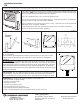
1. Open door frame by lifting rear of each latch assembly and hinging forward. Allow captive front cover
to hinge down. NOTE: If “TP” (tamperproof screws) option has been ordered, remove two tamperproof
(TP) screws before attempting to unlatch door frame. (FIGURE 1).
2. Unscrew 3 component cover screws and take off component cover.
3. Run service wire through cord entry on bottom of fixture. Make wire connections. On multiple volt-
age fixtures reference “TB” instructions below. (FIGURE 2).
4. Secure component cover to housing using same 3 screws. Latch front cover to housing. (Reinstall
tamperproof screws as required). (FIGURE 3).
5. The standard fixture comes with a yoke mounting bracket which can easily be mounted to a
variety of accessory mounting hardware. (FIGURE 4)
OPTIONAL MOUNTING
IS - Integral Slipfitter
The IS should be securely tightened to the end of a tenon or pipe 2” to 2-1/2” (2-3/8” to 2-7/8”
O.D.). Be certain the pivot retainer bolt is tightened securely after aiming is accomplished.
(FIGURE 5).
1-7/8”
(4.8cm)
2”
(5.1cm)
11/16” dia
(1.7cm)
3-3/4”
(9.5cm)
9/16” dia
(1.4cm)
Latches
(2)
Front
cover
TB - Tapped Ballast: The tapped ballast will be wired for 277 volt at the factory. To wire a fixture
that contains a tapped ballast, first determine correct line voltage. Then select the corresponding
fixture voltage lead, remove the crimped cap and connect to the supply voltage lead. The fixture
lead marked COM should be connected to the neutral supply lead for 120 or 277. For 208 or 240,
connect the other incoming hot leg to the fixture lead marked "COM". Be sure to cap off all unused
fixture leads individually.
Lamp Installation: Prior to installing the lamp in the fixture, check to be sure the lamp is of proper
type and wattage. Screw the lamp securely into the socket, back the lamp out one to two turns,
then screw the lamp back in, making sure it is secure. This properly seats the lamp in the socket.
FIGURE 1
FIGURE 2
FIGURE 3
FIGURE 4
FIGURE 5