
Installation Guide

Installation Instructions
TFR
Lithonia Lighting Outdoor
One Lithonia Way, Conyers, GA 30012
Phone: 800-279-8041 Fax: 770-918-1209
www.lithonia.com
Part Number: RJ5210130 Rev C
Revision Date: 5/30/12
©2001 Acuity Brands Lighting, Inc. All
Rights Reserved. Rev. 06/10
Delivery: Upon receipt of fi xture and accessories (packed separately), thoroughly
inspect for any freight damage. All damage should be reported to the delivery
carrier. Compare the catalog description listed on the packing slip with the fi xture
label on the inside of the housing to be sure you have received the correct mer-
chandise.
Lamp Installation: Loosen the 2 closing screws, hinge door assembly forward to access lamp compartment . Verify that the lamp source
and wattage corresponds with the fi xture and ballast label. HID -Screw the lamp securely into the socket, back it out one or two turns, and
tighten securely again. This procedure properly seats the lamp in the socket. Close door using the standard closing screws.
Troubleshooting: If this fi xture fails to operate properly, check to make sure: The proper lamp is installed correctly. • The fi xture is wired
correctly. • The lamp is not faulty. • The fi xture is grounded correctly. • The line voltage at the fi xture is correct.
Multi-tap Ballast (TB): The multi-tap ballast will be prewired for 277V at the factory. First determine the correct line voltage. Then select
the corresponding fi xture voltage lead, remove the crimped cap and connect to the supply voltage lead. The fi xture lead marked COM
should be connected to the neutral supply lead for 120 or 277. For 208 or 240, connect the other incoming hot leg to the fi xture lead marked
"COM". Be sure to cap off all unused fi xture leads individually.
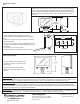
The standard fi xture comes with a yoke mounting bracket which can easily be mounted to a variety of accessory mounting hardware.
Yoke Detail
17-5/8”
(44.8 cm)
12-3/4”
(32.4 cm)
10-3/4”
(27.3 cm)
6”
(15.2 cm)
2”
(5.1 cm)
1-1/4”
(3.2 cm)
1-1/4”
(3.2 cm)
5/8”
(1.6 cm)
1/2”
(1.3 cm)
2 places
1. Mount fl oodlight to desired mounting hardware.
(See instruction sheet for Floodlighting Accessory/Mount-
ing.)
2. Loosen the 2 captive screws in front housing and allow
fi xture to hinge open.
3. Run service wire through cord entry on bottom of housing.
4. Make wire connections. For multi-tap ballast see instruc-
tions below.
5. Lamp fi xture per instructions below.
6. Close front housing, and tighten the 2 captive screws.
1. The IS should be securely tightened to
the end of a 1-1/4" to 2" (1-5/8" to 2-3/8" OD)
tenon or pipe.
2. Be certain the pivot retainer bolt is
tightened securely after aiming is accom-
plished.
Painted integral slipfi tter.