
Installation Guide

STEP-BY-STEP GUIDE
Page 3
Trouble Shooting Guide
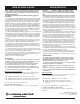
If this fi xture fails to operate properly, use the guide
below to diagnose and correct the problem.
Verify that fi xture is wired properly.
Verify that fi xture is grounded correctly.
Verify that the line voltage at the fi xture is correct.
If further assistance is required, contact:
Technical Support at: (800) 748-5070
This LED module does not require service or new bulbs to
change.
Note: Before beginning the installation, make sure all power is
off, shutting power off in breaker box to areas where downlights
are to be installed is recommended.
Required Tools (not included): Safety glasses and gloves.
1. Double check and measure the ceiling hole. Make sure it is the
correct size for outside rim of the luminaire to cover the hole while still
allowing the back of luminaire to sink in to the ceiling and springs to
hold fi rmly.
Remove existing retrofi t can if present or move it out of the way
since it will not be needed for installation.
If new hole is to be cut, use provided hole template. Place
template over the desired location. Trace the outer ring with a pen
or pencil (not included). Cut the opening with a saw (not included).
(Figure 1)
2. Open the cover of the remote driver box. Push and remove one of
the knockouts on the side plate.
Locate power supply leads from remote driver box and connect to
power source using wago connectors (provided).
Connect black wire to live wire, white wire to neutral wire, and
green wire with ground (as shown) and secure using wago connector.
Close the cover of the box. (Figure 2)
3. Connect the remote driver box to the light fi xture and tighten the
nut connector by hand. Arrow on the male and female parts of the con-
nector between the driver and fi xture cable should match. (Figure 3)
4. Place remote driver box thru the cut-out hole If remote driver box
need to be attached, use provided keyhole fi ttings on the back of
the box to hang it using round head screw (not included). (Figure 4)
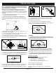
Figure 1 / Figura 1 / Schéma 1
5. Pull the spring clip on the fi xture up and through the ceiling
hole and place module in the hole making sure the spring clips
are holding securely. (Figure 5)
6. Turn the power back on. If the module doesn’t illuminate
within 5 seconds, turn power off, carefully remove the module and
double check all wiring and replace. (Figure 6)
WARNING:
DO NOT PLACE YOUR HAND UNDERNEATH SPRING CLIP
DURING REMOVAL PROCESS. SNAPPING OF THE CLIPS CAN
CAUSE INJURIES TO THE HAND. (Figure 7)
DO NOT USE ANY OTHER DRIVER EXCEPT LITHONIA
LIGHTING DRIVER THAT IS INCLUDED WITH THE FIXTURE.
DO NOT CONNECT MULTIPLE MODULES TO ONE DRIV-
ER.
DO NOT OPEN THE MODULE AND SIDE PLATE OF THE
REMOTE DRIVER BOX - NO SERVICEABLE PARTS INSIDE.
Figure 6 / Figura 6 / Schéma 6
Figure 3 / Figura 3 / Schéma 3
THREAD
LOCK
Figure 7 / Figura 7 / Schéma 7
DO NOT
DO NOT
PLACE YOUR
PLACE YOUR
HAND
HAND
DO NOT
DO NOT
PLACE YOUR
PLACE YOUR
HAND
HAND
Figure 5 / Figura 5 / Schéma 5
PULL UP
THROUGH
CEILING
HOLE
Figure 4 / Figura 4 / Schéma 4
ATTACH USING PROVIDED
KEYHOLE FITTINGS
(MOUNTING
OPTIONAL)
ROUND HEAD SCREWS
SIDE WALL
Figure 2 / Figura 2 / Schéma 2
ACCESS
NEUTRAL WIRE
(FROM POWER SUPPLY)
GROUND WIRE
(FROM POWER SUPPLY)
LIVE WIRE
(FROM POWER SUPPLY)
CONNECT GROUND WIRE USING WAGO CONNECTOR
(ROMEX CABLE)
wago
connector
wago
connector
wago
connector
NEUTRAL WIRE
GROUND WIRE
LIVE WIRE
NEUTRAL
WIRE
(WHITE)
GROUND
WIRE
(BARE COPPER /
GREEN)
LIVE
WIRE
(BLACK)
(FROM POWER SUPPLY)
(FROM DRIVER BOX)