TE Circuit Protection’s PolySwitch radial-leaded products represent the most comprehensive and complete set of PPTC products available in the industry today.
Application Selection Guide for Radial-leaded Devices The guide below lists PolySwitch radial-leaded devices that are typically used in these applications. Specifications for the suggested device part numbers can be found in this section. Once a part number has been selected, the user should evaluate and test each product for its intended application.
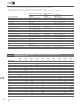
Product Series - Current Rating, Voltage Rating / Typical Resistance for Radial-leaded Devices BBRF 99V Voltage Rating RXEF 72V RKEF 60V RXEF 60V RUEF 30V RGEF 16V RHEF 16V RHEF 30V Cont’d RUSBF 16V RUSBF 6V Hold Current (A) 2.000 — — — — — — 0.0610Ω — — — 2.500 — 0.065Ω 0.063Ω — 0.030Ω 0.0380Ω — — 0.030Ω — 3.000 — 0.050Ω 0.040Ω — 0.035Ω 0.0514Ω 0.0430Ω — — — 3.750 — 0.040Ω 0.029Ω — — — — — — — 4.000 — — 0.026Ω — 0.020Ω 0.0300Ω 0.
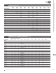
Table R2 Thermal Derating for Radial-leaded Devices [Hold Current (A) at Ambient Temperature (°C)] Cont’d Maximum Ambient Temperature Part Number -40°C -20°C 0°C 20°C 25°C 40°C 50°C 60°C 70°C 85°C 125°C RKEF 60V RKEF050 0.73 0.65 0.58 0.50 0.48 0.42 0.38 0.34 0.31 0.26 — RKEF065 0.94 0.85 0.75 0.65 0.63 0.54 0.50 0.44 0.40 0.34 — RKEF075 1.09 0.98 0.86 0.75 0.73 0.62 0.58 0.51 0.46 0.39 — RKEF090 1.30 1.17 1.04 0.90 0.87 0.75 0.69 0.61 0.55 0.
Thermal Derating for Radial-leaded Devices [Hold Current (A) at Ambient Temperature (°C)] Cont’d Maximum Ambient Temperature Part Number -40°C -20°C 0°C 20°C 25°C 40°C 50°C 60°C 70°C 85°C 125°C RHEF 16V - High Temperature RHEF200 2.71 2.49 2.26 2.06 2.00 1.77 1.60 1.46 1.34 1.11 0.49 RHEF300 4.07 3.74 3.41 3.09 3.00 2.65 2.40 2.21 2.00 1.66 0.74 RHEF400 5.57 5.11 4.65 4.22 4.00 3.62 3.29 3.01 2.73 2.27 1.01 RHEF450 6.10 5.60 5.10 4.60 4.50 4.00 3.
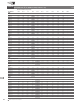
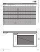
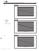
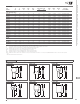
Figure R1-R5 Thermal Derating Curve for Radial-leaded Devices Cont’d Figure R2 RKEF % of rated hold and trip current 200 150 100 50 0 -40 -20 0 20 40 60 80 Ambient Temperature (˚C) B = RUSBF075, RUSBF120, RUSBF155 RUEF, and all other RUSBF Figure R3 200 % of Rated Hold and Trip Current A = 150 B A 100 A 50 B 0 -40 -20 0 20 40 60 80 Ambient Temperature (˚C) Figure R4 RHEF 200 % of Rated Hold and Trip Current 12 150 100 50 0 -40 -20 0 20 40 60 Ambient Temperature
PolySwitch Resettable Devices – Radial-leaded Devices Figure R1-R5 Thermal Derating Curve for Radial-leaded Devices Cont’d Figure R5 RGEF % of Rated Hold and Trip Current 200 150 100 50 0 -40 -20 0 20 40 60 80 Ambient Temperature (˚C) Table R3 Electrical Characteristics for Radial-leaded Devices IH (A) IT (A) VMAX (V) IMAX (A) PD Typ (W) RMIN (Ω) RMAX (Ω) R1MAX (Ω) Lead Size [mm2 (AWG)] 0.55 1.10 99 20 1.5 1.60 60 0.8 1.30 1.95 [0.520mm2 (20)] RXEF005 0.05 0.
Table R3 Electrical Characteristics for Radial-leaded Devices IH (A) IT (A) RKEF050 0.50 1.00 60 40 1.00 8.00 0.8 0.320 0.529 0.900 [0.205mm2 (24)] RKEF065 0.65 1.30 60 40 1.25 8.00 1.0 0.250 0.450 0.720 [0.205mm2 (24)] RKEF075 0.75 1.50 60 40 1.40 8.00 1.5 0.200 0.390 0.640 [0.205mm2 (24)] RKEF090 0.90 1.80 60 40 1.50 8.00 2.0 0.190 0.320 0.520 [0.205mm2 (24)] RKEF110 1.10 2.20 60 40 2.20 8.00 3.0 0.170 0.280 0.470 [0.520mm2 (20)] RKEF135 1.
Part Number IH (A) IT (A) VMAX (V) IMAX (A) PD Typ (W) Max. Time-to-trip (A) (s) Cont’d RMIN (Ω) RMAX (Ω) R1MAX (Ω) Lead Size [mm2 (AWG)] RHEF* 16V - High Temperature RHEF200 2.0 3.8 16 100 1.4 10.0 4.3 0.0450 0.07400 0.1100 [0.205mm2 (24)] RHEF300 3.0 6.0 16 100 3.0 15.0 5.0 0.0330 0.05300 0.0790 [0.520mm2 (20)] RHEF400 4.0 7.5 16 100 3.3 20.0 5.0 0.0240 0.04000 0.0600 [0.520mm2 (20)] RHEF450 4.5 7.8 16 100 3.6 22.5 3.0 0.0220 0.03600 0.0540 [0.
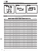
Figure R6-R14 Dimension Figures for Radial-leaded Devices Figure R12 Cont’d Figure R13 A Figure R14 E A C B J E J H D C CL to CL F CL CL Table R4 Dimensions & Weights for Radial-leaded Devices Dimensions in Millimeters (Inches) A Part Number 12 144 B C Max. Min. Max. BBRF 99V BBRF550 — 10.9 (0.43) — 14.0 (0.55) 4.3 5.8 (0.17) (0.23) 7.6 (0.3) RXEF 60V RXEF005 — — RXEF010 — RXEF017 — 8.0 (0.32) 7.4 (0.29) 7.4 (0.29) 8.3 (0.33) 11.6 (0.46) 12.7 (0.50) 4.3 5.8 (0.17) (0.
Cont’d Dimensions in Millimeters (Inches) A Part Number B C D Min. Max. Min. Max. Min. Max. Min. RKEF 60V RKEF050 — — RKEF065 — RKEF075 — RKEF090 — RKEF110 — RKEF135 — RKEF160 — RKEF185 — RKEF250 — RKEF300 — RKEF375 — RKEF400 — RKEF500 — 7.10 (0.28) 7.11 (0.28) 7.87 (0.31) 7.87 (0.31) 7.60 (0.30) 10.20 (0.40) 12.20 (0.48) 13.00 (0.51) 14.00 (0.55) 16.50 (0.65) 16.50 (0.65) 21.00 (0.83) 24.10 (0.95) 11.43 (0.45) 12.20 (0.48) 12.20 (0.48) 13.97 (0.55) 15.00 (0.59) 17.
Table R4 Dimensions & Weights for Radial-leaded Devices Cont’d Dimensions in Millimeters (Inches) A Part Number RUSBF 16V RUSBF090 Max. Min. Max. Min. — 7.4 (0.29) 7.4 (0.29) 8.9 (0.35) 8.9 (0.35) 10.2 (0.40) 11.4 (0.45) — 12.2 (0.48) 14.2 (0.56) 13.5 (0.53) 15.2 (0.60) 15.7 (0.62) 18.3 (0.72) 4.3 (0.17) 4.3 (0.17) 4.3 (0.17) 4.3 (0.17) 4.3 (0.17) 4.3 (0.17) 5.8 (0.23) 5.8 (0.23) 5.8 (0.23) 5.8 (0.23) 5.8 (0.23) 5.8 (0.23) 7.6 (0.30) 7.6 (0.30) 7.6 (0.30) 7.6 (0.30) 7.6 (0.30) 7.6 (0.30) 12.
Cont’d Dimensions in Millimeters (Inches) A Part Number Min. B Max. RHEF 16V - High Temperature RHEF1000 — 17.5 (0.69) RHEF1100 — 21.0 (0.83) RHEF1300 — 23.5 (0.925) RHEF1400 — 23.5 (0.925) RHEF1500 — 23.5 (0.925) RUSBF 6V RUSBF075 — 6.9 (0.27) RUSBF120 — 6.9 (0.27) RUSBF155 — 6.9 (0.27) C D E Min. Max. Min. Max. Min. Max. Min. — 26.5 (1.04) 26.1 (1.03) 28.7 (1.13) 28.6 (1.13) 28.7 (1.13) 9.4 (0.37) 9.4 (0.37) 9.4 (0.37) 9.4 (0.37) 9.4 (0.37) 10.9 (0.43) 10.9 (0.43) 10.9 (0.43) 10.9 (0.
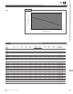
Figure R15-R21 Typical Time-to-trip Curves at 20°C for Radial-leaded Devices Figure R16 RXEF005 RXEF010 RXEF017 RXEF020 RXEF025 RXEF030 RXEF040 RXEF050 RXEF065 J K L M N O P Q R = = = = = = = = = RXEF075 RXEF090 RXEF110 RXEF135 RXEF160 RXEF185 RXEF250 RXEF300 RXEF375 B 1000 C D E F G H I J K L M NO P Q R 100 A 10 Time-to-trip (s) RXEF A = B = C = D = E = F = G = H = I = Cont’d R Q P 1 O N M L K J I H 0.1 0.01 A 0.001 0.
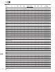
Cont’d Figure R19 RGEF (data at 25°C) A = RGEF250 B = RGEF300 C = RGEF400 D = RGEF500 E = RGEF600 F = RGEF700 G = RGEF800 H = RGEF900 I = RGEF1000 J = RGEF1100 K = RGEF1200 L = RGEF1400 A 1000 B C D E F GH I J K L 100 Time-to-trip (s) 10 L K J I H G F 1 A 0.1 E D C 0.01 B 0.
Table R5 Physical Characteristics and Environmental Specifications for Radial-leaded Devices BBRF Physical Characteristics Lead material Soldering characteristics Solder heat withstand Insulating material Operation temperature Tin-plated copper, 0.52mm2 (20AWG), ø0.81mm (0.032in.
PolySwitch Resettable Devices – Radial-leaded Devices Table R5 Physical Characteristics and Environmental Specifications for Radial-leaded Devices Cont’d RKEF Environmental Specifications Test Conditions Resistance Change Passive aging -40°C, 1000 hours ±5% 85°C, 1000 hours ±5% Humidity aging 85°C, 85%RH, 1000 hours ±10% Thermal shock 85°C, -40°C (10 times) ±10% Solvent resistance MIL-STD-202, Method 215F No change RUEF Physical Characteristics Lead material RUEF090 to RUEF250: Tin-plat
Table R5 Physical Characteristics and Environmental Specifications for Radial-leaded Devices RGEF Physical Characteristics RGEF250: Tin-plated copper-clad steel, 0.205mm2 (24AWG), ø0.51mm/0.020in. Lead material RGEF300 to RGEF1100 : Tin-plated copper, 0.52mm2 (20AWG), ø0.81mm/0.032in. RGEF1200 to RGEF1400 : Tin-plated copper, 0.82mm2 (18AWG), ø1.0mm/0.04in.
Part Number Bag Quantity Tape & Reel Quantity Ammo Pack Quantity Standard Package Quantity Part Marking Agency Recognition BBRF 99V BBRF550 BBRF550-2 500 — — 10,000 BF550 UL, CSA — 1,500 — 7,500 BF550 UL, CSA RXEF 60V RXEF005 500 — — 10,000 — UL, CSA, TÜV RXEF005-2 — 3,000 — 15,000 — UL, CSA, TÜV RXEF005-AP — — 2,000 10,000 — UL, CSA, TÜV 500 — — 10,000 XF010 UL, CSA, TÜV RXEF010-2 — 3,000 — 15,000 XF010 UL, CSA, TÜV RXEF010-AP — — 2,000 10,000 XF01
Table R6 Packaging and Marking Information for Radial-leaded Devices Part Number Bag Quantity Tape & Reel Quantity Ammo Pack Quantity Standard Package Quantity Part Marking Cont’d Agency Recognition RXEF 72V RXEF250 250 — — 5,000 XF250 UL, CSA, TÜV RXEF250-2 — 1,000 — 5,000 XF250 UL, CSA, TÜV RXEF250-AP — — 1,000 5,000 XF250 UL, CSA, TÜV 250 — — 5,000 XF300 UL, CSA, TÜV RXEF300-2 — 1,000 — 5,000 XF300 UL, CSA, TÜV RXEF300-AP — — 1,000 5,000 XF300 UL, CSA, TÜV
Part Number Bag Quantity Tape & Reel Quantity Ammo Pack Quantity Standard Package Quantity Cont’d Part Marking Agency Recognition RUEF 30V RUEF700 250 — — 5,000 UF700 UL, CSA, TÜV, CQC RUEF700-2 — 1,000 — 5,000 UF700 UL, CSA, TÜV, CQC RUEF700-AP — — 1,000 5,000 UF700 UL, CSA, TÜV, CQC 250 — — 5,000 UF800 UL, CSA, TÜV, CQC RUEF800-2 — 1,000 — 5,000 UF800 UL, CSA, TÜV, CQC RUEF800-AP — — 1,000 5,000 UF800 UL, CSA, TÜV, CQC 250 — — 5,000 UF900 UL, CSA, TÜV,
Table R6 Packaging and Marking Information for Radial-leaded Devices Part Number Bag Quantity Tape & Reel Quantity Ammo Pack Quantity Standard Package Quantity Part Marking Cont’d Agency Recognition RGEF 16V RGEF700 500 — — 10,000 GF700 UL, CSA, TÜV RGEF700-2 — 1,500 — 7,500 GF700 UL, CSA, TÜV RGEF700-AP — — 1,500 7,500 GF700 UL, CSA, TÜV 500 — — 10,000 GF800 UL, CSA, TÜV RGEF800-2 — 1,000 — 5,000 GF800 UL, CSA, TÜV RGEF800-AP — — 1,000 5,000 GF800 UL, CSA, T
Part Number Bag Quantity Tape & Reel Quantity Ammo Pack Quantity Standard Package Quantity Part Marking Cont’d Agency Recognition RHEF 16V - High Temperature RHEF900 250 — — 5,000 HF9 UL, CSA, TÜV RHEF900-2 — 1,000 — 5,000 HF9 UL, CSA, TÜV RHEF900-AP — — 1,000 5,000 HF9 UL, CSA, TÜV 250 — — 5,000 HF10 UL, CSA, TÜV RHEF1000-2 — 1,000 — 5,000 HF10 UL, CSA, TÜV RHEF1000-AP — — 1,000 5,000 HF10 UL, CSA, TÜV 250 — — 5,000 HF11 UL, CSA, TÜV RHEF1100-2 — 1,0
Table R7 Tape and Reel Specifications for Radial-leaded Devices RXEF, BBRF and RKEF devices are available in tape and reel packaging per EIA468-B/IEC60286-2 standards. See Figures R22 and R23 for details. Description EIA Mark Dimension (mm) Tolerance Carrier tape width W 18 -0.5/+1.0 Hold-down tape width W4 11 Minimum Top distance between tape edges W6 3 Maximum Sprocket hole position W5 9 -0.5/+0.75 Sprocket hole diameter D0 4 ± 0.
Cont’d RUEF and RUSBF devices are available in tape and reel packaging per EIA468–B/IEC60286–2 standards. See Figures R22 and R23 for details. Description EIA Mark Dimension (mm) Carrier tape width W 18 Tolerance -0.5/+1.0 Hold-down tape width W4 11 Minimum Top distance between tape edges W6 3 Maximum Sprocket hole position W5 9 -0.5/+0.75 Sprocket hole diameter D0 4 ± 0.2 Abscissa to plane (straight lead)* (RUEF300 to RUEF900) H 18.5 ± 2.
Table R7 Tape and Reel Specifications for Radial-leaded Devices Cont’d RGEF and RHEF devices are available in tape and reel packaging per EIA468–B/IEC60286–2 standards. See Figures R22 and R23 for details. Description EIA Mark Dimension (mm) Carrier tape width W 18 -0.5/+1.0 Hold-down tape width W4 11 Minimum Top distance between tape edges W6 3 Maximum Sprocket hole position W5 9 -0.5/+0.75 Sprocket hole diameter D0 4 ± 0.
PolySwitch Resettable Devices – Radial-leaded Devices Figure R22 EIA Referenced Taped Component Dimensions for Radial-leaded Devices Dh Dp Dh Dp Reference plane H1 P1 H1 F A L H0 B D4 C2 C1 H W5 W I2 L1 P0 Direction of unreeling D0 Cross section A-B t Figure R23 EIA Referenced Reel Dimensions for Radial-leaded Devices Reel Upper side n Type a Direction of unreeling Lower side c w1 Cross section w2 Optional shape: Circular or polygonal Part Numbering System for Radial-leaded Devices
12 Warning : • Users should independently evaluate the suitability of and test each product selected for their own application. • Operation beyond the maximum ratings or improper use may result in device damage and possible electrical arcing and flame. • These devices are intended for protection against damage caused by occasional overcurrent or overtemperature fault conditions and should not be used when repeated fault conditions or prolonged trip events are anticipated.