
Datasheet
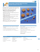

PolySwitch Resettable Devices – Radial-leaded Devices
143
RoHS Compliant, ELV Compliant
12
RHEF*
16V - High Temperature
RHEF200 2.0 3.8 16 100 1.4 10.0 4.3 0.0450 0.07400 0.1100 [0.205mm
2
(24)]
RHEF300 3.0 6.0 16 100 3.0 15.0 5.0 0.0330 0.05300 0.0790 [0.520mm
2
(20)]
RHEF400 4.0 7.5 16 100 3.3 20.0 5.0 0.0240 0.04000 0.0600 [0.520mm
2
(20)]
RHEF450 4.5 7.8 16 100 3.6 22.5 3.0 0.0220 0.03600 0.0540 [0.520mm
2
(20)]
RHEF550 5.5 10.0 16 100 3.5 27.5 6.0 0.0150 0.02500 0.0370 [0.520mm
2
(20)]
RHEF600 6.0 10.8 16 100 4.1 30.0 5.0 0.0130 0.02150 0.0320 [0.520mm
2
(20)]
RHEF650 6.5 12.0 16 100 4.1 32.5 5.5 0.0110 0.01750 0.0260 [0.520mm
2
(20)]
RHEF700 7.0 13.0 16 100 4.0 35.0 7.0 0.0100 0.01640 0.0250 [0.520mm
2
(20)]
RHEF750 7.5 13.1 16 100 4.5 37.5 7.0 0.0094 0.01530 0.0220 [0.520mm
2
(20)]
RHEF800 8.0 15.0 16 100 4.2 40.0 8.0 0.0080 0.01350 0.0200 [0.520mm
2
(20)]
RHEF900 9.0 16.5 16 100 5.0 45.0 10.0 0.0074 0.01200 0.0170 [0.520mm
2
(20)]
RHEF1000 10.0 18.5 16 100 5.3 50.0 9.0 0.0062 0.01050 0.0150 [0.520mm
2
(20)]
RHEF1100 11.0 20.0 16 100 5.5 55.0 11.0 0.0055 0.00900 0.0130 [0.520mm
2
(20)]
RHEF1300 13.0 24.0 16 100 6.9 65.0 13.0 0.0041 0.00690 0.0100 [0.823mm
2
(18)]
RHEF1400 14.0 27.0 16 100 6.9 70.0 13.0 0.0030 0.00600 0.0090 [0.823mm
2
(18)]
RHEF1500 15.0 28.0 16 100 7.0 75.0 20.0 0.0032 0.00613 0.0092 [0.823mm
2
(18)]
RUSBF
6V
RUSBF075 0.75 1.30 6 40 0.3 8.0 0.4 0.110 0.1750 0.23 [0.205mm
2
(24)]
RUSBF120 1.20 2.00 6 40 0.6 8.0 0.5 0.070 0.0975 0.14 [0.205mm
2
(24)]
RUSBF155 1.55 2.65 6 40 0.6 7.8 2.2 0.040 0.0705 0.10 [0.205mm
2
(24)]
Part
Number
I
H
(A)
I
T
(A)
V
MAX
(V)
I
MAX
(A)
P
D Typ
(W)
R
MIN
(Ω)
R
1MAX
(Ω)
Lead Size
[mm
2
(AWG)]
R
MAX
(Ω)
Max.Time-to-trip
(A) (s)
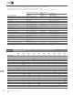
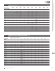
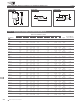
Notes:
I
H
: Hold current: maximum current device will pass without interruption in 20°C still air.
I
T
: Trip current: minimum current that will switch the device from low resistance to high resistance in 20°C still air.
V
MAX
: Maximum continuous voltage device can withstand without damage at rated current.
I
MAX
: Maximum fault current device can withstand without damage at rated voltage.
P
D
: Power dissipated from device when in the tripped state in 20°C still air.
R
MIN
: Minimum resistance of device as supplied at 20°C unless otherwise specified.
R
MAX
: Maximum resistance of device as supplied at 20°C unless otherwise specified.
R
1MAX
:
Maximum resistance of device when measured one hour post reflow (surface-mount device) or one hour post trip (radial-leaded device) at 20°C unless otherwise specified.
* Electrical characteristics determined at 25°C.
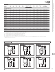
A
B
D
C
C
to
L
C
L
C
L
C
L
E
F
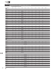
Figure R6
A
B
D
C
C
to
L
C
L
C
L
C
L
E
F
Figure R7
A
B
D
CF
C
to
L
C
L
C
L
C
L
E
Figure R8
A
B
D
C
C
to
L
C
L
C
L
C
L
F
E
Figure R9
A
B
D
C
C
to
L
C
L
C
L
C
L
E
F
Figure R10
B
D
CF
C
to
L
C
L
C
L
C
L
A
E
Figure R11
Table R3 Electrical Characteristics for Radial-leaded Devices
Cont’d
Figure R6-R14 Dimension Figures for Radial-leaded Devices