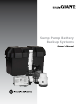
Sump Pump Battery Backup Systems Owner’s Manual
Before Getting Started Read and follow safety instructions. Refer to product data plate(s) for additional operating instructions and specifications. s This is the safety alert symbol. When you see this ! symbol on your pump or in this manual, look for one of the following WARNING signal words and be alert to the potential for personal injury or property damage if ignored: s WARNING DANGER ! warns about hazards that will cause serious personal injury, death or major property damage if ignored.
Table of Contents Getting Started . . . . . . . . . . . . . . . . . . . . . . . . . . . . . . . . . . . . . . . . . . . . . . . . . . . . . . . . . . . . . . . . . . . . . . . . . . . . . . . . . . . . 4 Specifications . . . . . . . . . . . . . . . . . . . . . . . . . . . . . . . . . . . . . . . . . . . . . . . . . . . . . . . . . . . . . . . . . . . . . .
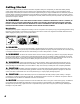
Getting Started This owner’s manual provides you with the information required to safely own and operate your Little Giant battery backup system. Retain these instructions for future reference. The Little Giant battery backup system you have purchased is of the highest quality workmanship and material, and has been engineered to give you long and reliable service. Little Giant pumps are carefully tested, inspected, and packaged to ensure safe delivery and operation.
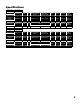
Specifications Item Number Model Number 506406 SPBS-10HF Charging Unit Item Number 106469 Model Number Volts Hz Max Input Amps at 115 VAC Max Output Amps at 12 VDC Watts Cord (ft) Weight (lb) Battery Leads (ft) Backup Pump Switch 1210HF 115 VAC 60 3 10 345 6 5 6 Model Number Volts Hz Switch On Level Switch Off Level Watts Cord (ft) Weight (lb) Battery Leads (ft) 105601 RS-12 12 VDC - 13.5" 9" - 9 0.
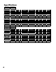
Specifications Item Number Model Number 506411 SPBS-10HF-6 Item Number Model Number Volts Hz Max Input Amps at 115 VAC Max Output Amps at 12 VDC Watts Cord (ft) Weight (lb) Battery Leads (ft) 106469 1210HF 115 VAC 60 3 10 345 6 5 6 Charging Unit Backup Pump AMPS Item Number Model Number Volts Hz FLA Start Watts Cord (ft) Weight (lb) Battery Leads (ft) 106963 2500 12 VDC - 14 32 168 6 6 - Item Number Model Number Volts Hz Switch On Level Switch Off Level W
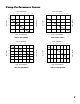
Pump Performance Curves FLOW - LITERS/MINUTE 30 60 90 120 150 0 180 20 40 80 100 120 140 160 7.5 20 6 20 6 15 4.5 15 4.5 10 3 10 3 0 0 10 20 30 40 HEAD - FEET 25 5 1.5 5 0 0 1.
Installation of a Backup System on a Common Discharge (For 12 VDC Backup Systems SPBS-10HF and SPBS-12HF which do not include a 115 V primary sump pump assembly) s ! WARNING Comply with all national and local electrical and plumbing codes when installing this unit.
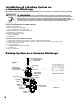
s ! WARNING CAUTION Reduction of plumbing sizes from what is used for the discharges of the primary 115 VAC pump and 12 VDC pump can result in system underperformance. Discharge piping that is of insufficient size can result in premature pump and/ or system operation failure. Figure 2 Drill 3/16" hole Step 1 Step 2 Step 3 Step 4 Step 5 Step 6 ! NOTICE: Do not glue any parts until the entire assembly, including primary pump, has been dry-assembled to verify fits.
Step 6 a. Cable Ties (1) and (2) will be used to attach the 12 VDC pump control switch housing and power cord to the discharge pipe. Installing both cable ties to 12 VDC pump control switch is critical for proper operation of 12 VDC pump. (see Figure 1). b. Thread cable tie (1) through the eyelets on the 12 VDC pump control switch housing. c. Position the 12 VDC pump control switch on the discharge pipe such that cable tie (1) is 4" to 6" above the “ON” water level of the 115 VAC primary pump. d.
Installation of a Backup System on a Separate Discharge (For 12 VDC Backup Systems SPBS-10HF and SPBS-12HF which do not include a 115 V primary sump pump assembly) ! WARNING s Comply with all national and local electrical and plumbing codes when installing this unit.
s ! WARNING CAUTION Reduction of plumbing sizes from what is used for the discharges of the primary 115 VAC pump and 12 VDC pump can result in system under performance. Discharge piping that is of insufficient size can result in premature pump and/or system operation failure. Figure 4 Drill 3/16" hole Step 1 Step 2 Step 3 Step 4 Step 5 Step 6 ! NOTICE: Do not glue any parts until the entire assembly, including primary pump, has been dry-assembled to verify fits.
Step 6 a. Cable ties (1) and (2) will be used to attach the 12 VDC pump control switch housing and power cord to the discharge pipe. Installing both cable ties to 12 VDC pump control switch is critical for proper operation of 12 VDC pump. (See Figure 3). b. Thread cable tie (1) through the eyelets on the 12 VDC pump control switch housing. c. Position the 12 VDC pump control switch on the discharge pipe such that cable tie (1) is 4" to 6" above the “ON” water level of the 115 VAC primary pump. d.
Installation of Pre-assembled Backup System on a Common Discharge (For 12 VDC Backup Systems SPBS-10HF-6 and SPBS-12HF-10 with included 115 VAC Primary Pump) ! WARNING s Comply with all national and local electrical and plumbing codes when installing this unit.
Charger/Controller Unit Installation Charger/Controller Electrical Ratings: Input: 120 VAC, 3 Amp Output (Maximum Charging Current): • Model 1210HF: 12 VDC, 10 Amps • Model 1212HF: 12VDC, 12 Amps Use only with 12 VDC deep cycle battery rated 85 – 140Ah, lead-acid or AGM s ! WARNING Do not use in explosive atmospheres. Do not handle Charger/Controller Unit with wet hands or when standing on a wet or damp surface, or in water.
Charger/Controller Unit Installation (continued) Step 1 – Mounting the Charger/Controller Unit ! NOTICE: Do not expose the charger to excessive moisture. Install charger in a dry location. Indoor use only. s a. Complete all plumbing, pump installation and pump control switch installation before installing the Charger/Controller Unit and before beginning work on the electrical connections to the Charger/Controller Unit or the battery. b.
Charger/Controller Unit Installation (continued) Step 2 – Electrical Connections ! WARNING s Comply with all national and local electrical and plumbing codes when installing this unit. Disconnect power from all electrical equipment housed within the sump system before working on or around the sump pump or battery backup system beginning with 115 VAC powered pumps, level switches, and charger controllers; followed by DC powered items.
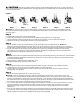
Charger/Controller Unit Operation Charged Power 75% Charging 50% Pump Run 25% High Water Low Battery Replace Fuse RESET Reset button will reset pump run light. System is ready for use. Manually activates pump to ensure proper operation TEST SILENCE Press silence to deactivate audible alarm Figure 10 1. The upper left side of the face plate provides an approximation of the battery charge. In normal operation the charge will typically show 25%, 50%, and 75% lights lit.
Sump System Operation Testing ! WARNING Always disconnect the electrical power before touching the pump or discharge when water is s present in the area of the pump. Failure to do so can result in hazardous electrical shock. ! WARNING s CAUTION Ensure all hose clamp connections and threaded connections are tight and that all plumbing slip fit connections are properly glued prior to starting the sump pump system.
System Maintenance: ! WARNING s Disconnect power from all electrical equipment housed within the sump system before working on or around the sump pump or battery backup system beginning with 115 VAC powered pumps, level switches, and charger controllers; followed by DC powered items. Includes all items such as pumps, level control switches, Charger/Controller Unit, and battery systems. ! WARNING s CAUTION The backup pump and the primary pump are designed for pumping clear water only.
Troubleshooting PROBLEM TROUBLESHOOTING INFORMATION PROBABLE CAUSES Bad connection 115 V 12 V X X Plug-in pump X Turn on circuit breaker or replace fuse Blown fuse Pump does not turn on or turn off. Bad battery X Replace battery Pump impeller obstructed X X Pull pump and clean Pump control switch X X Replace switch X When power is restored, the charger will charge the battery Low battery Pump does not deliver rated capacity. Pump will not shut off.
LIMITED WARRANTY THIS WARRANTY SETS FORTH THE COMPANY’S SOLE OBLIGATION AND PURCHASER’S EXCLUSIVE REMEDY FOR DEFECTIVE PRODUCT. Franklin Electric Company, Inc. and its subsidiaries (hereafter “the Company”) warrants that the products accompanied by this warranty are free from defects in materials or workmanship of the Company that exist at the time of sale by the Company and which occur or exist within the applicable warranty period.
WARRANTIES OF MERCHANTABILITY AND/OR FITNESS FOR A PARTICULAR PURPOSE, WHICH ARE HEREBY SPECIFICALLY DISCLAIMED AND EXPRESSLY EXCLUDED. CORRECTION OF NON-CONFORMITIES, IN THE MANNER AND FOR THE PERIOD OF TIME AS SET FORTH ABOVE, SHALL CONSTITUTE FULFILLMENT OF ALL LIABILITY OF THE COMPANY TO THE PURCHASER WHETHER BASED ON CONTRACT, NEGLIGENCE, OR OTHERWISE.
For technical assistance, please contact . . . . . . . . . . . . . . . . . 800.701.7894 www.littlegiant.com lgnet@fele.com Franklin Electric Co., Inc. Form 998912 Rev. 0 08.15 Oklahoma City, OK 73157-2010 Phone: 1.800.701.7894 Fax: 1.405.228.