
User Guide


The flexible jacketed cord assembly mounted to the pump must
not be modified in any way, with the exception of shortening the
cord to fit into a control panel. Any splice between the pump and
the control panel must be made within a junction box and mount-
ed outside of the basin, and comply with the National Electrical
Code. Do not use the power cord for lifting the pump.
The pump motor is equipped with an automatic resetting thermal
protector and may restart unexpectedly. Protector tripping is an
indication of motor overloading as a result of operating the pump
at low heads (low discharge restriction), excessively high or low
voltage, inadequate wiring, incorrect motor connections, or a defective
motor or pump.
1. Read all instructions and Safety Guidelines thoroughly. Failure
to follow the guidelines and instructions could result in serious
bodily injury and/or property damage.
2. DO NOT USE TO PUMP FLAMMABLE OR EXPLOSIVE FLUIDS
SUCH AS GASOLINE, FUEL OIL, KEROSENE, ETC. DO
NOT USE IN EXPLOSIVE ATMOSPHERES OR HAZARDOUS
LOCATIONS AS CLASSIFIED BY NEC, ANSI/NFPA70. FAILURE
TO FOLLOW THIS WARNING CAN RESULT IN PERSONAL
INJURY AND/OR PROPERTY DAMAGE.
3. During normal operation the pump is immersed in water. Also,
during rain storms, water may be present in the surrounding
area of the pump. Caution must be used to prevent bodily injury
when working near the pump:
a. The plug must be removed from the receptacle prior to
touching, servicing or repairing the pump.
b. To minimize possible fatal electrical shock hazard, extreme
care should be used when changing fuses. Do not stand in
water while changing fuses or insert your finger into the fuse
socket.
4. Do not run the pump in a dry basin. If the pump is run in a dry
basin, the surface temperature of the pump will rise to a high
level. This high level could cause skin burns if the pump is
touched and will cause serious damage to your pump.
5. Do not oil the motor. The pump housing is sealed. A high
grade high temperature dielectric oil devoid of water has been
put into the motor housing at the factory. Use of other oil could
cause serious electric shock and/or permanent damage to
the pump.
6. This pump’s motor housing is filled with a dielectric lubricant
at the factory for optimum motor heat transfer and lifetime
lubrication of the bearings. Use of any other lubricant could
cause damage and void the warranty. This lubricant is non-
toxic; however, if it escapes the motor housing, it should be
removed from the surface quickly by placing newspapers or
other absorbent material on the water surface to soak it up, so
aquatic life is undisturbed.
7. Allow pump to cool (4 hours minimum) prior to servicing. The
oil is pressurized at elevated temperatures.
INSTALLATION
Pump must be installed in a suitable basin which is at least 18"
in diameter and 24" deep, and installed in accordance with local
electrical and plumbing codes.
The HT-10E Series Effluent Pumps feature a 1-1/2" female NPT
discharge.
Pump can be installed with materials capable of withstanding 200°F
water. Proper adapters are required to connect piping to pump.
Pump must be placed with its base on a hard level surface. Never
place pump directly on clay, earth or gravel surfaces.
A check valve must be used in the discharge line to prevent back
flow of liquid into the basin. The check valve should be a free flow
valve that will easily pass solids.
CAUTION: For best performance of check valves, when handling
solids install in a horizontal position or at an angle of no more than
45°. Do not install check valve in a vertical position, as solids may
settle in valve and prevent opening on start-up.
When a check valve is used drill a 3/16" hole in the discharge pipe
approximately 1" to 2" above the pump discharge connection and
below check valve to prevent air locking of the pump.
WIRING
Check local electrical and building codes before installation. The
installation must be in accordance with their regulations as well as
the most recent National Electrical Code (NEC).
To conform to the National Electrical Code all pumps must be
wired with 14 AWG or larger wire. For runs to 250', 14 AWG wire
is sufficient. For longer runs, consult a qualified electrician or the
factory.
Pump should be connected or wired to its own circuit with no other
outlets or equipment in the circuit line. Fuses and circuit breaker
should be of ample capacity in the electrical circuit. See chart below.
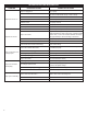
H.P. VOLTAGE
FUSE OR CIRCUIT
BREAKER AMPS
1/2 115 20
FLOAT SWITCH LEVEL CONTROL
The FS series pumps are equipped with an integral float switch
level control for automatic operation. This level control uses a
mechanical switch sealed in a specially designed high temperature
float cylinder.
When the level rises in the basin, the cylinder floats up with the
level. When the cylinder position is at an angle of about 45°, the
pump starts.
As the level draws down, the cylinder floats down and when it is
again at an angle of about 45°, the pump stops.
NOTE: BE CERTAIN PUMP IS SECURE IN BASIN AND CYLINDER
FLOATS UNOBSTRUCTED WITHOUT TOUCHING THE BASIN
WALLS OR PLUMBING.
2
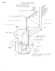
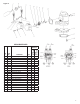
Figure 2.