
User Guide


3
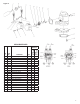
REMOTE FLOAT SWITCH INSTALLATION
1. The float switch consists of three parts: a) mechanical switch;
b) cord clamp; c) clamp screw.
NOTE: If screw is lost, use a #10-24 x 1/2" long tapping
screw.
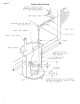
2. Attach cord clamp to pump cover as shown in Figure 1. The
clamp must be positioned as shown to allow free operation of
float. Be sure to locate pump and switch power cords away
from switch float.
3. A 5" tether length is recommended. When a tether length of 5"
is used, a minimum basin diameter of 18" is recommended.
The tether length is measured as shown in Figure 3.
4. After desired tether length is established, hand-tighten clamp
screw.
5. TESTING: Plug switch into outlet without water in basin. Lift
float and watch for pump to operate. Do not run pump for
more than 5 seconds.
OPERATION
TESTING PUMP OPERATION
FS SERIES AUTOMATIC PUMPS
1. These pumps are equipped with a float-operated switch.
2. When these pumps are installed in a basin with a sealed
cover, switch operation cannot be observed. The sump cover
usually will have a spare hole that is plugged with a rubber
plug. This plug can be removed and switch operation can be
observed.
3. Run water into pump until pump starts.
4. Be sure gate valve in discharge line is open.
5. Allow pump to operate through several on-off cycles.
MANUAL PUMPS
The pump cord for these pumps can be plugged directly into a
properly grounded receptacle with voltage consistent with pump
nameplate for continuous pump operation.
CAUTION: This type of operation should be used only for emer-
gency use or when a large volume of water is to be pumped.
Pump must not be allowed to run dry. If pump is run dry, it may
damage pump an void the warranty.
MAINTENANCE AND SERVICE
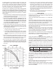
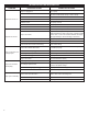
If pump does not operate properly, consult the Troubleshooting
Chart. If trouble cannot be located with these steps shown, con-
sult your pump dealer or take pump to a Little Giant authorized
service center.
NOTE: Relay Cover Mounting Screws (item #23) requires 15-20
in-lbs. torque.
CAUTION: When working on pump or switch, always unplug
pump power cord in addition to removing fuse or shutting off circuit
breaker before working on pump.
CLEANING IMPELLER AND VOLUTE
WARNING: DO NOT REMOVE THE 3 SOCKET-HEAD CAP SCREWS.
THE MOTOR SECTION OF YOUR PUMP IS PERMANENTLY
LUBRICATED WITH DIELECTRIC OIL AND SEALED AT THE
FACTORY. REMOVAL OF THESE SOCKET-HEAD CAP SCREWS
BY ANYONE OTHER THAN AN AUTHORIZED LITTLE GIANT SERVICE
CENTER WILL BREAK THIS SEAL AND VOID THE WARRANTY.
1. On 10E Series Effluent pumps: Remove 5 screws (item 18 on
parts list) that hold screen base and base plate to volute/plate.
2. Clean impeller and volute passage. Do not use strong solvents
on impeller.
3. Be sure impeller turns freely after cleaning.
4. WARNING: DO NOT REMOVE IMPELLER. WARRANTY IS VOID
IF MOTOR HOUSING, IMPELLER OR SEALS HAVE BEEN
REMOVED.
ANY REPAIR ON MOTOR MUST BE DONE BY AN AUTHORIZED
LITTLE GIANT SERVICE CENTER.