
Use and Care Manual


3
Installing the Control Unit/Pump:
THE EC-1 PUMP IS NOT SUBMERSIBLE. Ensure that it is located
where water cannot be splashed, sprayed, or dripped onto it.
DO NOT locate the pump near insulation or other flammable material.
1. Determine a suitable location to install pump. Pump can be
located above, below or adjacent to air handler.
a. The maximum suction lift of the pump is 3 ft (1m), therefore
the control unit/pump cannot be installed more than 3 ft
(1m) higher (vertically) than the collection reservoir.
2. Using the supplied mounting bracket, secure bracket to wall
using supplied wall anchors and screws.
3. Using one of the supplied #4 x 1" long self-tapping screws,
insert the end of the screw into the hole of the mounting
grommet in the pump bracket and work the point down to
pierce through the mounting grommet. Perform this step for
the second mounting grommet.
4. Place the pump mounting bracket against the wall and use the
points of the screw to mark the wall in locations to drill for the
wall anchors.
5. If using the supplied wall anchors, drill a 3/16" (5mm) hole x 1"
(26mm) deep at each point marked on the wall, then insert an
anchor fully into each hole.
6. Using the supplied screws, attach the mounting bracket to
the wall. Hand-tighten the wall anchor screws against rubber
grommet being careful so that screw head does not push
through rubber grommet.
7. Slide pump onto wall bracket by inserting slots of bracket into
flanges of black mounting grommets on side of pump housing.
8. Connect the sensor cable from the collection reservoir to the
control unit/pump by inserting the cable connector into the
corresponding socket on the control unit/pump.
Drain Hose-to-Reservoir Inlet Tubing:
1. Connect ½" ID x 3" (12mm ID x 76mm) tubing to the air handler
drain hose.
2. If the air handler’s drain hose has a plastic adapter suitable
for use with reservoir inlet tubing, there is no need to use the
stepped adapter to connect drain hose to reservoir inlet.
3. If the drain hose has plastic adapter not suitable for use with
the reservoir inlet tubing, it may be necessary to cut the hose
and remove the adapter. Connect the single-sized end of
stepped adapter to the inlet tubing, and fit the stepped adapter
to the drain hose. The adapter fits 1/2", 5/8" and 3/4" (14mm,
16mm, 18mm, 20mm) drain hose ID. Use a cable tie or hose
clamp to secure the drain hose to the adapter.
4. If the condensate drain has a metal drain port, such as on a fan
coil, use the supplied adapter and connect it to the metal drain
port using a flexible hose (not supplied).
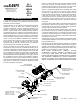
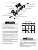
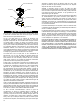
PUMP INTAKE
PUMP
DISCHARGE
POWER CORD
CONNECTION
1.8" [46]
1.8" [46]
2.4" [61]
A-N536
4.1" [104]
SENSOR CABLE
CONNECTION
ARROW INDICATES
FLOW DIRECTION
5. Be certain to support the reservoir when attaching tubing and
that tubing is not kinked when reservoir is in place.
Reservoir-to-Pump Tubing:
1. For convenience, the reservoir assembly is equipped with three
outlet ports, one vertical and two horizontal. Choose an outlet
port on the reservoir assembly, remove port cap and connect
the 5/32" ID x 3 ft (4mm ID x 1m) tubing onto selected port.
a. Confirm that all unused outlet ports are capped off (with the
provided port caps) or leakage from the reservoir will occur
.
2. Use supplied cable tie to secure the tubing.
3. Route the tubing to pump intake (indicated by the direction of
flow arrow on the top of pump) and connect.
4. Use supplied cable tie to secure tubing to pump intake port.
5. Be certain the tubing is not kinked when pump is installed.
Pump Discharge Tubing:
The EC-1 pump is supplied with a section of silicone discharge
tubing attached to the pump discharge and fitted with a ¼" (6mm)
tubing adaptor. Do not remove tubing.
1. Connect a length of ¼" (6mm) ID discharge tubing (not
provided) to the discharge tubing adaptor using a cable tie or
hose clamp.
2. The other end of discharge tubing is to be directed into the
nearest inside gravity-feed drain, or along the refrigeration
lines to an outside gravity-feed drain.
3. Maximum acceptable horizontal run of discharge tubing is
dependent on the diameter of tubing used and the vertical lift.
The installer should apply a reasonable factor of safety and
size the pump to handle a greater flow rate than the maximum
condensate to be produced.
4. Do not extend the discharge tubing more than 33 ft (10m)
above the level of the pump.
5. NOTE: The end of the discharge tubing must be positioned
such that it is no more than 3 ft (1m) below (vertically) the
collection reservoir. Otherwise, a siphon effect may occur
causing the pump to lose its prime. This condition would cause
the pump to re-prime itself during each cycle, resulting in noisy
operation and shortened pump life.
6. Ensure that there are no kinks, twists or breaks in the
discharge tubing that could cause blockage. If cable ties are
used to strap tubing to structures, assure that cable ties do not
crush or squeeze-closed the tubing.
Vent Tubing:
1. Connect the ¼" ID (6mm) tubing to the vent port of the reservoir
cover. The free end of the vent tubing must be secured above
the highest level of the drip tray in the air conditioner to prevent
overflow.
2. Route the vent tubing upward ensuring that it is not kinked or
blocked.
3. Do not remove, cut off, shorten, twist, or sharply bend the
vent tube.
4. Do not connect this tube to the air handler; it is for venting only.
5. Be certain that the vent tubing will remain in an upward
position during the operating life of the pump.
General Installation Notes:
• After connecting the reservoir inlet, reservoir-to-pump, vent
and discharge tubing, ensure that the reservoir and pump
remain positioned correctly.
• Keep all tubing and wires clear of moving parts in the air handler.
• Upon completion of the installation, test the pump and all