LITTLE WONDER ® Shredding Models 8221 and 8271 © 2007 Little Wonder, Div. of Schiller-Pfeiffer Inc. All Rights Reserved.
Table of Contents Important Information Important Information A. Introduction Introduction.................................................................1 Service Information.....................................................1 Special Safety Information.........................................1 Safety and Warnings Safety Decals.............................................................
Safety and Warnings Keep hands and feet away from air discharge areas. Rotating fan will cause serious injury. A. Safety Decals In order to keep operators of the Shredding TruckLoader informed regarding safety and/or unit operation, decals (labels) have been placed on various parts of the unit. Adherence to the warnings and instructions depicted or otherwise conveyed in these decals is absolutely essential to the safe operation of the Shredding TruckLoader.
General Safety Rules 1. Read and understand manual. 2. Wear eye, hearing, and breathing protection, proper clothing and footwear. 3. While operating the machine, maintain a safe operating position, secure footing and good balance at all times. 4. Keep area clear of children, pets and bystanders. 5. Never attempt to use an incomplete machine or one fitted with an unauthorized modification. 6. Avoid contact with and inhalation of harmful fluids, gases, mists, fumes, and dust. 7.
C. Engine/ Fuel Warnings - “Don’ts” Don’t fuel engine or check fuel while smoking or near an open flame or other ignition source. Stop engine and be sure it is cool before refueling. Don’t leave the engine running while the Shredding TruckLoader is unattended. Don’t transport the Shredding Truckloader while the engine is running. Don’t start, run this TruckLoader indoors, or in an improperly ventilated area as poisonous carbon monoxide and other gasses are emitted.
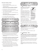
Assembly Instructions: A. Hose Assembly (Figure #1) 1. Remove the Hose from the box. 2. With the assistance of a second person, hold the hose at both ends and stretch it out as far as possible. This will maximize the hose length and open the internal diameter. 3. Insert the Hose Flange Assembly into one of the open ends as shown. 4. Using one of the Hose Clamps, secure the hose to the Hose Flange Assembly by wrapping the clamp around the hose portion covering the Hose Flange and tighten. 5.
C. Mounting the Boom Arm Assembly to the Housing Boom Column (Figure #3) 1. Slide a Thrust Washer (720428) onto the shaft of the Boom Column Assembly. 5. Secure the Boom Arm Assembly and Washers to the shaft with a Lock Nut (720580). 2. Apply some #2 lithium based grease to the shaft of the Boom Column. 6. 3. Install the Boom Arm Assembly (720285.17) onto the shaft of the Boom Column Assembly.
Knobs previously installed. E. Changing the direction of the Discharge Chute (Figure #4) 1. Loosen the Knobs (38524) by hand and, if needed, the Nuts (64229-03) with a 1/2” wrench. 2. Rotate the Discharge Chute to the desired position. 3. Retighten the Knobs by hand and the Nuts, if loosened, with the 1/2” wrench. 3. Since the Hose Assembly may be rotated 360 degrees, orient the Intake Nozzle to your preferred position and lock it in place. 4.
G. Attaching the Chain Loop Assembly to the Boom Arm Assembly (Figure #6) H. Attaching the Hose Band to the Chain Loop Assembly (Figure #6) 1. Slip the threaded end of the Chain Loop Assembly (720290) through the hole found at the end of the Boom Arm Assembly (720285.17). 1. After wrapping the Hose Band around the Hose, insert the Bolt (64123-61) through the holes in the Hose Band. 2. Once through, secure the Chain Loop Assembly with the Nut (64229-05). 2.
L. Discharge Extension Kit Assembly Instructions Contents Included in Kit: Operation: A. Starting the Engine 1. Discharge Extension Hose (720436) 1. Check the oil level. Add oil if necessary. 2. Hose Clamp (720388) 2. Check the air cleaner for dirty, loose, or damaged parts. Clean or replace parts as necessary. Tools Needed: 1. 9/16” Box Wrench or Socket Wrench w/ 9/16” Socket 3. 2.
a) Turn off the engine and wait until all moving parts have come to a complete stop. b) Disconnect the spark plug wires from the spark plugs on the engine. c) Remove the Hose Assembly from the Inlet Flange Assembly. With this removed, open the Inlet Flapper and remove any debris that is clogging the housing. CAUTION SHOULD BE USED WHEN CLEARING DEBRIS FROM INSIDE THE HOUSING. GLOVES SHOULD BE WORN AS SHARP EDGES ON THE FAN, THE TALON RING, OR IN THE DEBRIS MAY BE PRESENT.
a. Gasoline/Alcohol blends: Gasohol (up to 10% ethyl alcohol, 90% unleaded gasoline by volume) is approved as a fuel for Kohler engines. Other gasoline/alcohol blends are not approved. b. Gasoline/Ether blends: Methyl Tertiary Butyl Ether (MTBE) and unleaded gasoline blends (up to a maximum of 15% MTBE by volume) are approved as a fuel for Kohler engines. Other gasoline/ether blends are not approved. 2. Fuel Warnings: Gasoline is extremely flammable and its vapors can explode if ignited.
Maintenance: A. Removing and Replacing the Fan and Talon Ring (Figure #7) 9. Reinstall the Fan onto the crankshaft and orient it to the same position as removed in Step #6. Once the Fan is aligned properly with the keyways of the Fan hub and engine crankshaft in line, slide the Fan completely onto the crankshaft. 1. Disconnect the spark plug wires from the spark plugs on the engine. 2. Disconnect safety switch wire from engine. 3. Unbolt and Remove the Inlet Assembly from the face of the Housing.
B. Liner Replacement (Figure #7) 1. Complete Steps 1 thru 7 found in section A (Removing and Replacing the Fan and Talon Ring). 2. Unbolt and remove the hardware securing the Liner to the Housing. 3. Remove the Liner from the housing by wrapping it and pulling it through the front of the housing. 4. When installing the new Liner into the Housing, make sure the chamfered edge of the liner is installed in the vertical position at the discharge opening of the housing. 5.
D. Heavy-Duty Air Cleaner 1. E. Spark Plug Every 250 hours of operation (more often under extremely dusty or dirty conditions), replace the main paper element and check inner element. Follow these steps. a) Unhook the two retaining clips and remove the end cap from the air cleaner housing. b) Pull the air cleaner element out of the housing. See Removing Elements Figure. c) After the main element is removed, check the condition of the inner element.
Storage: A. Preparing for Long-Term (Two Months or More) Storage 1. Clean the exterior surfaces of the unit (including engine). 2. Change the Oil and Filter while the engine is still warm. 3. The fuel system must be completely emptied, or the gasoline must be treated with a stabilizer to prevent deterioration. To empty the fuel system, drain the fuel tank and carburetor or run the engine until the tank and system are empty. Drained fuel may only be stored for 30 days.
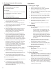
44 34 45 X9 30 47 64 39 34 55 62 63 60 57 61 56 59 50 X2 52 58 X2 49 48 51 34 53 43 54 42 37 41 28 38 31 40 81 39 X2 10 29 X4 77 36 X4 34 X10 33 X10 23 39 X2 21 24 35 32 22 X10 8 X4 25 X2 3 9 X4 26 X4 27 2 10 X2 6 X4 4 5 X4 14 X4 1 7 X4 11 13 X4 12 X4 10 X4 15 16 20 X4 17 19 18 Base Unit View 16
Model #8221 & 8271 Part Numbers Balloon Item # Part # Description 1 720903 22 HP KOHLER ENGINE 1 720904 27 HP KOHLER ENGINE 2 720483 OIL DRAIN VALVE 3 64163-34 3/8” SQ. x 3” LG KEY 4 720451.17 PAINTED SKID FRAME 5 64123-234 3/4-10 x 4” LG HEAVY HEX CAP SCREW 6 64268-07 3/4-10 GRADE G LOCK FLANGE NUT 7 720279 1-1/4” ROUND TUBE PLUG 8 64123-82 WASHER, FLAT .406 X 1.411 X 9GA 9 64213-31 3/8 SAE FLAT WASHER 10 64141-4 3/8-16 WIZ NUT 11 720491 GAS TANK 12 64123-75 3/8” x 1-3/4” LG.
Model #8221 & 8271 Part Numbers Balloon Item # 49 50 51 52 53 54 55 55 56 57 58 59 60 61 62 63 63 64 65 66 67 68 69 69 70 70 71 71 72 72 73 74 75 76 77 78 79 80 81 Part # Description 720258.10 FLAPPER RETAINER 154 5/16-18 FEMALE THREADED KNOB 720234.17 PAINTED SWITCH PLATE 90-0532 5/16-18 x 4” LG GRADE 8 BOLT 720482 SAFETY SWITCH WIRE ASSEMBLY 48228-3A CLIP WIRE HARNESS 720377.17 12” INLET FLAPPER 720378.17 14” INLET FLAPPER 720285.
2 year limited Service & Warranty policy FOR GASOLINE POWERED for Shredding TruckLoader The Little Wonder Shredding TruckLoader is guaranteed against defects in material and workmanship for a period of TWO YEARS from date of purchase, when used for RESIDENTIAL SERVICE, or COMMERCIAL SERVICE. Any Little Wonder Shredding TruckLoader or part found to be defective within the warranty period is to be returned to any registered Little Wonder Dealer.