LITTLE WONDER ® EN OWNER’S MANUAL and SAFETY INSTRUCTIONS for Single Edged (Models 1910, 2410, 3010, 1912, 2412, 3012) and FR Double Edged (Models 1920, 2420, 3020, 1922, 2422, 3022) Electric Hedge Trimmers MANUEL DE L’UTILISATEUR et INSTRUCTIONS DE SÉCURITÉ à tranchant unique (modèles 1910, 2410, 3010, 1912, 2412 et 3012) et à double tranchant (modèles 1920, 2420, 3020, 1922, 2422 et 3022) Taille-haies électriques ES MANUAL DEL PROPIETARIO e INSTRUCCIONES DE SEGURIDAD para las unidades con una so
TABLE OF CONTENTS I. IMPORTANT INFORMATION A. Introduction .......................................................................................................2 Page II. GENERAL SAFETY RULES ............................................................................................3 A. Safety Decals......................................................................................................4 B. Safety Symbols Identification ....................................................................
II. GENERAL SAFETY RULES Warning: When using electric tools, basic safety precautions, including the following, should always be followed to reduce the risk of fire, electric shock and personal injury. Read all these instructions before operating this product and save these instructions. For safe operations: 1) Keep work area clean. Cluttered areas and benches invite injuries. 2) Consider work area environment. Do not expose power tools to rain. Do not use power tools in damp or wet locations.
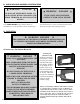
! WARNING DANGER ! ! THIS SYMBOL POINTS OUT IMPORTANT SAFETY INSTRUCTIONS. WHEN YOU SEE THIS SYMBOL, ! HEED IT’S WARNING!! STAY ALERT!! ! A. SAFETY DECALS AND MOLDED SYMBOLS Important parts of the safety system incorporated in both Single Edge and Double Edge trimmers are the warning and informational decals and molded-in symbols found on various parts of the trimmer. These decals must be replaced in time due to abrasion, etc.
! C. SPECIAL SAFETY RULES 1. Read and understand the owner’s manual. Pay particular attention to all sections regarding safety. 2. Always keep a firm grip on both handles while the blades are moving and/or the motor is running. On Single Edged units, the right hand grasps the front side handle and the left hand grasps the rear handle. On Double Edged units, one hand grasps the front ‘loop’ handle, while the other hand grasps the rear handle. ! D.
III. UNPACKING AND ASSEMBLY INSTRUCTIONS ! WARNING DANGER ! ! BLADES ARE EXTREMELY SHARP. TO AVOID INJURY WHEN UNPACKING THE HEDGE TRIMMER, DO NOT GRASP THE BLADES. Your Little Wonder hedge trimmer has been assembled for you at the factory. Before operating be WARNING DANGER ! IF YOU HAVE ANY QUESTIONS, CONTACT YOUR LOCAL DEALER sure all fasteners are secure, and all guards and safety devices are in place and operating properly. IV.
1. Read care and safety instructions carefully before attempting to use this trimmer. Only after you are familiar with your hedge trimmer and all of its controls and the functions should you start the trimmer. 2. Before plugging into an electric circuit, be sure that the voltage supply is as specified on hedge trimmer. Models 1910, 1920, 2410, 2420, 3010, 3020 are rated at 464 watts at 115 volts. Models 1912, 1922, 2412, 2422, 3012, 3022 are rated at 390 watts at 230 volts. 3.
VI. SERVICE A. TROUBLE SHOOTING Problem Cause Remedy 1. Blades don’t cut cleanly. Blades are dull or not adjusted properly. Have blades sharpened and adjusted. 2. Blades don’t move when turned on. Blades are adjusted too tight. Re-adjust blades following service instructions. 3. Excessive electrical arcing from vents in top of trimmer. Worn brushes. Replace brushes - follow service instructions. B.
Single Edge Assembly KEY # 1 2 2 2 3 4 5 5 5 6 6 6 7 7 7 8 9 9 9 10 10 10 11 12 PART # 310100 16-54B 16-54B 16-54B 310106 NA 310310 310305 310300 30-2 24-2 19-2 30-1 24-1 19-1 310215 16-93 16-93 16-93 16-54A 16-54A 16-54A 3036-B 310505 DESCRIPTION Gear Housing Assembly (including pressed in pins) Nut Lock 1/4-28 whiz Flange (for models 3010, 3012) 30” SE Nut Lock 1/4-28 whiz Flange (for models 2410, 2412) 24” SE Nut Lock 1/4-28 whiz Flange (for models 1910, 1912) 19” SE Frame Bar Support Side Handle Asse
Double Edge Assembly KEY # 1 2 2 2 3 4 5 5 5 6 6 6 7 7 7 8 8 8 9 9 9 10 11 10 PART # 310100 16-54B 16-54B 16-54B 300300 NA 310325 310320 310315 30-2D 24-2D 19-2D 30-1D 24-1D 19-1D 30-42 24-42 19-42 16-54A 16-54A 16-54A 310500 310505 DESCRIPTION Gear Housing Assembly (including pressed in pins) Nut Lock 1/4-28 whiz Flange (for models 3020, 3022) 30” DE Nut Lock 1/4-28 whiz Flange (for models 2420, 2422) 24” DE Nut Lock 1/4-28 whiz Flange (for models 1920, 1922) 19” DE Frame Bar Support Loop Handle Assemb
Gear/Motor Assembly KEY NO. 1 2 3 4 5 6 7 8 9 10 11 12 13 14 14 15 17 18 18 19 20 21 22 PART NO.
Double Edge Front Loop Handle Assembly KEY # 1 2 3 4 5 6 7 8 PART # 3033 310405 310219 310203 310207 310504 310500 310218 DESCRIPTION Switch Normally Open Switch Normally Closed Loop Handle Trigger Set Loop Handle Set Shield Screw Plasti-Tite #8 x 1” Screw Plasti-Tite #8 x 3/4” Loop Handle Trigger Strap QTY.
Main Housing Assembly KEY NO. 1 2 3 5 5 5 5 6 7 8 9 10 11 11 11 12 13 PART NO.
VIII. SPECIFICATIONS Model 1912 1922 2412 2422 3012 3022 Cutting Length cm (in.) 48 (19) 48 (19) 61 (24) 61 (24) 76 (30) 76 (30) Weight kg (lb) 3.49 (7.7) 3.89 (8.6) 3.62 (8.0) 4.04 (8.9) 3.85 (8.5) 4.59 (10.1) The A-weighted emission sound pressure level at the operator position has been measured at: LPA = 80 dB(A). These measurements were made in accordance with EN ISO 11201:1996 under no-load conditions. The Hand-Arm weighted r.m.s.
LITTLE WONDER ® EN OWNER’S MANUAL and SAFETY INSTRUCTIONS for Single Edged (Models 1910, 2410, 3010, 1912, 2412, 3012) and FR Double Edged (Models 1920, 2420, 3020, 1922, 2422, 3022) Electric Hedge Trimmers MANUEL DE L’UTILISATEUR et INSTRUCTIONS DE SÉCURITÉ à tranchant unique (modèles 1910, 2410, 3010, 1912, 2412 et 3012) et à double tranchant (modèles 1920, 2420, 3020, 1922, 2422 et 3022) Taille-haies électriques ES MANUAL DEL PROPIETARIO e INSTRUCCIONES DE SEGURIDAD para las unidades con una so
TABLE DES MATIÈRES I. INFORMATION IMPORTANTE A. Introduction .......................................................................................................2 Page II. CONSIGNES GÉNÉRALES DE SÉCURITÉ ...........................................................................3 A. Autocollants de sécurité ...................................................................................4 B. Identification des symboles de sécurité............................................................4 C.
II. RÈGLES GÉNÉRALES DE SÉCURITÉ Avertissement : Pendant l’utilisation d’outils électriques, il convient de toujours prendre des précautions élémentaires, y compris celles qui sont indiquées ci-dessous, pour réduire les risques d’incendie, de choc électrique et de blessures corporelles. Lisez toutes les instructions ci-dessous avant d’utiliser ce produit, et conservez-les pour des consultations ultérieures. Pour une utilisation sûre : 1) Maintenez la propreté de la zone de travail.
AVERTISSEMENT DANGER ! ! ! CE SYMBOLE ATTIRE VOTRE ATTENTION SUR D’IMPORTANTES CONSIGNES DE SÉCURITÉ. LORSQUE VOUS VOYEZ CE SYMBOLE, TENEZ COMPTR DE L’AVERTISSEMENT ! SOYEZ VIGILANT ! A. AUTOCOLLANTS DE SÉCURITÉ ET Des éléments importants du dispositif de sécurité incorporé dans les taille-haies à simple et double tranchant sont les autocollants d’avertissement et d’information et les symboles moulés que l’on retrouve sur différentes parties de l’appareil.
! C. RÈGLES PARTICULIÈRES DE SÉCURITÉ 1. Veuillez lire et comprendre le manuel d'instructions. Accordez une attention particulière à toutes les sections relatives à la sécurité. 2. Gardez toujours une prise ferme sur les deux poignées lorsque les lames bougent et/ou le moteur tourne. Dans le cas d’un appareil à tranchant unique, tenez la poignée latérale avant de la main droite et la poignée arrière de la main gauche.
III. INSTRUCTIONS DE DÉBALLAGE ET DʼASSEMBLAGE AVERTISSEMENT DANGER ! ! ! LES LAMES SONT EXTRÊMEMENT COUPANTES. POUR ÉVITER DE SE BLESSER PENDANT LE DÉBALLAGE DU TAILLE-HAIES, NE PAS LE SAISIR PAR LES LAMES. Le taille-haies Little Wonder a été assemblé pour vous à l’usine. Avant de le faire fonctionner, assurezvous que toutes les attaches sont bien serrées et que AVERTISSEMENT DANGER ! SI VOUS AVEZ LA MOINDRE QUESTION, NʼHÉSITEZ PAS À CONSULTER VOTRE REVENDEUR LOCAL.
1. 2. 3. 4. 5. Lisez attentivement les instructions d’entretien et de sécurité avant d’utiliser ce taille-haies. Ne le démarrez pas avant d’en avoir pris une connaissance générale et d’en connaître toutes les commandes et les fonctions. Avant de le brancher sur un circuit électrique, vérifiez que la tension d’alimentation du circuit est conforme à celle qui est indiquée sur l’appareil.
VI. ENTRETIEN A. LOCALISATION DES PANNES Problème Cause Correction 1. Les lames ne coupent pas proprement. Les lames sont émoussées ou ne sont pas réglées correctement. Faites affûter et ajuster les lames. 2. Les lames ne bougent pas lorsque l’appareil est mis en marche. Les lames sont trop serrées. Réajustez les lames conformément aux consignes de réglage 3. Production excessive d’étincelles par les trous d’aération à la partie supérieure de l’appareil. Les balais sont usés.
Assemblage à tranchant unique INSTALLER LE FIL DEPUIS LE POINT DANS LE CHEMIN DE CÂBLE NO DE REP. NO DE RÉF.
Ensemble à double tranchant NO DE REP. NO DE RÉF.
Ensemble réducteur-moteur NO DE REP. NO DE RÉF.
Ensemble poignée annulaire avant pour taillehaies à double tranchant NORMALEMENT FERMÉ CONNECTER LES FILS NOIRS JEU DE (3) NORMALEMENT OUVERT CONNECTER LES FILS ROUGES NO DE REP. NO DE RÉF.
Ensemble carter principal CONNECTER LE FIL ROUGE VERS LES INTERRUPTEURS AVANT CONNECTER LE FIL NOIR NO DE REP. NO DE RÉF.
VIII. CARACTÉRISTIQUES TECHNIQUES Modèle 1912 1922 2412 2422 3012 3022 Longueur de coupe en cm (po) 48 (19) 48 (19) 61 (24) 61 (24) 76 (30) 76 (30) Poids en kg (lb) 3,49 (7,7) 3,89 (8,6) 3,62 (8,0) 4,04 (8,9) 3,85 (8,5) 4,59 (10,1) Tous les taille-haies mentionnés sont conçus pour une alimentation sous 230 volts à 50 hertz. La mesure du niveau de pression acoustique pondéré A au poste de l’opérateur est de : LPA = 80 dB(A).
LITTLE WONDER ® EN OWNER’S MANUAL and SAFETY INSTRUCTIONS for Single Edged (Models 1910, 2410, 3010, 1912, 2412, 3012) and FR Double Edged (Models 1920, 2420, 3020, 1922, 2422, 3022) Electric Hedge Trimmers MANUEL DE L’UTILISATEUR et INSTRUCTIONS DE SÉCURITÉ à tranchant unique (modèles 1910, 2410, 3010, 1912, 2412 et 3012) et à double tranchant (modèles 1920, 2420, 3020, 1922, 2422 et 3022) Taille-haies électriques ES MANUAL DEL PROPIETARIO e INSTRUCCIONES DE SEGURIDAD para las unidades con una so
ÍNDICE DE MATERIAS I. INFORMACIÓN IMPORTANTE A. Introducción.......................................................................................................2 Página II. REGLAS GENERALES DE SEGURIDAD .............................................................................3 A. Etiquetas engomadas de salvaguardias.............................................................4 B. Identificación de los símbolos de seguridad ....................................................4 C.
II. NORMAS GENERALES DE SEGURIDAD Advertencia: Durante el uso de las herramientas eléctricas, deberán aplicarse en todo momento las precauciones básicas para su seguridad, que incluyen además la disminución del riesgo de provocar un incendio, exponerse a una descarga eléctrica o lesionarse. Lea y conserve todas estas instrucciones, antes de operar este producto. Salvaguardas de la operación: 1) Mantenga limpia el área de trabajo.
ADVERTENCIA PELIGRO ! ESTE SÍMBOLO INDICA LAS INSTRUCCIONES IMPORTANTES PARA SU SEGURIDAD. ¡¡RESPETE LA ADVERTENCIA INDICADA CUANDO VEA ESTE SÍMBOLO!! ¡¡MANTÉNGASE ALERTA!! A. ETIQUETAS MOLDEADOS ! ENGOMADAS Y SÍMBOLOS Podadoras con una sola cuchilla Etiqueta engomada con el número de serie Interruptores de encendido y apagado (On/Off) B.
! C. REGLAS ESPECIALES DE SEGURIDAD 1. Leer y entender el contenido del manual del propietario. Prestarle atención particularmente a todas las secciones relacionadas con la seguridad. 2. Mantener siempre la podadora firmemente sujetada con ambas empuñaduras, mientras las cuchillas está en movimiento y/o cuando el motor esté funcionando. En las unidades con una sola cuchilla, la mano derecha deberá sujetar la empuñadura delantera lateral, y con la mano izquierda sujetar la empuñadura posterior.
III. INSTRUCCIONES PARA DESEMPACARLA Y ENSAMBLARLA ! ADVERTENCIA PELIGRO ! LAS CUCHILLAS ESTÁN EXTREMADAMENTE FILOSAS. PARA EVITAR LESIONARSE AL DESEMPACAR LA PODADORA DE ARBUSTOS, EVITE SUJETARLA POR LAS CUCHILLAS. Su podadora de arbustos Little Wonder ha sido previamente ensamblada en la fábrica. Antes de operarla asegúrese de que todos los dispositivos ADVERTENCIA PELIGRO ! SI TUVIESE ALGUNA DUDA, COMUNÍQUESE CON SU DISTRIBUIDOR EN SU LOCALIDAD.
1. 2. 3. 4. 5. Lea cuidadosamente las instrucciones de conservación y seguridad, antes de intentar utilizar esta podadora. Solamente después de que usted se haya familiarizado con su podadora de arbustos, todos sus controles y funcionamiento, podrá hacerla funcionar. Antes de conectarla a un circuito eléctrico, asegúrese de que el abastecimiento del voltaje sea igual al especificado en la podadora.
VI. SERVICIO A. CORRECCIÓN DE POSIBLES AVERÍAS Problema Causa 1. Las cuchillas no cortan los arbustos eficientemente. Las cuchillas están desafiladas o no están ajustadas apropiadamente. Haga que se afilen y ajusten las cuchillas. 2. Las cuchillas no se mueven al poner en marcha el motor. Las cuchillas están demasiado ajustadas. Reajuste las cuchillas siguiendo las instrucciones de servicio. 3. Arcos voltaicos excesivos procedentes de las ventilas en la parte superior de la podadora.
Ensamble con una sola cuchilla INSTALE EL CABLE DEL A TRAVÉS DEL CABLE CLAVE # 1 2 2 2 3 4 5 5 5 6 6 6 7 7 7 8 9 9 9 10 10 10 11 12 COMP.
Ensamble con dos cuchillas CLAVE # 1 2 2 2 3 4 5 5 5 6 6 6 7 7 7 8 8 8 9 9 9 10 11 10 COMP.
Ensamble del engranaje/motor REF. # 1 2 3 4 5 6 7 8 9 10 11 12 13 14 14 15 17 18 18 19 20 21 22 COMP.
Ensamble de la empuñadura de rizo delantera con dos cuchillas NORMALMENTE CERRADO CONECTE LOS CABLES NEGROS JUEGO DE (3) NORMALMENTE ABIERTO A LA TARJETA PC CONECTE LOS CABLES COLOR ROJO CLAVE # 1 2 3 4 5 6 7 8 COMP. # 3033 310405 310219 310203 310207 310504 310500 310218 DESCRIPCIÓN Interruptor normalmente abierto Interruptor normalmente cerrado Juego del gatillo de la empuñadura de rizo Juego de la empuñadura de rizo Blindaje Tornillo, Plasti-Tite #8 x 1 pulg.
Ensamble de la carcasa principal CONECTE EL CABLE COLOR ROJO EN LOS INTERRUPTORES DEL FRENTE CONECTE EL CABLE COLOR NEGRO REF. # 1 2 3 5 5 5 5 6 7 8 9 10 11 11 11 12 13 COMP.
VIII. ESPECIFICACIONES Modelo 1912 1922 2412 2422 3012 3022 Longitud de corte Peso cm (pulg.) kg (lb) 48 (19) 3.49 (7.7) 48 (19) 3.89 (8.6) 61 (24) 3.62 (8.0) 61 (24) 4.04 (8.9) 76 (30) 3.85 (8.5) 76 (30) 4.59 (10.1) Todas las podadoras de arbustos están clasificadas para 230 voltios CA a 50 hertzios. La emisión del nivel de presión del ruido A fue medida según la postura del operario y resultó ser: LPA = 80 dB(A).