INSTALLATION MANUAL Gujarat : 1800-2582-583 | Maharashtra : 1800-1024-212 Punjab/Himachal/J & K : 1800-1377-781 | South India: 1800-1200-666 | Rest of India : 1800-1020-666
Dear Customer Congratulations on being the proud owner of Lloyd Air Conditioner. Your Air Conditioner comes with Lloyd Guarantee of Quality.
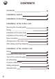
CONTENTS Contents 1 Installation sketch 2 Installation instructions 3 Installation of the indoor unit Securing the mounting plate Wiring Installation of the drain hose Installation of the indoor unit Pipe connection Arrangement of the drain hose Wall sealing and Pipe fastening 3 4 4 5 5 5 5 Installation of the outdoor unit Wiring Installation of the drain joint Joint of the connecting pipe Air exhausting Process of flared tube Adding refrigerant Operation test 1 6 9 9 9 9 10 10
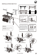
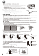
INSTALLATION SKETCH Confirm the installation position by the mark of the indoor mounting plate. or above 105m 155mm above 250mm m or or The connecting pipe can be led from back, right, underside, or left-back side.
INSTALLATION INSTRUCTIONS 1 Location of indoor unit Keep the air inlet and outlet at a far distance from the blockage. Keep the height distance between the indoor and outdoor unit at most 5m. Mount on the wall solid enough to bear the weight of the unit and not cause any shake. Avoid direct sunshine. A place easy for condensate drain and easy for connecting with the outdoor unit. Keep a far distance away from the fluorescent lamp, it may influence the operation of remote controller.
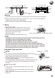
fasten string at the central hole fasten string at the central hole at least 250mm 40mm at least 180mm Center of hole(? 65mm) plumb 120mm 440mm 440mm at least 80mm at least 120mm ¦ at least 120mm 230mm at least 140mm 90mm plumb Pipe hole Center of hole(? 65mm) ¦ 90mm Pipe hole NOTICE: The holes at solid arrow position must be secured to avoid the shake of mounting plate.
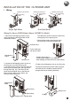
READJUSTMENT OF DRAIN HOSE If pipe comes out of the left side of the indoor unit, the drain hose must be refitted, otherwise water leakage may occur. Readjustment methods: Interchange the position of drain hose and drain rubber plug. Clearance is not allowed after refit, it would lead to water leakage. Drain rubber plug drain hose 4 Installation of the indoor unit Indoor unit Let pipe go through the wall hole and attach the indoor unit to the mounting plate.
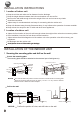
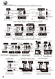
INSTALLATION OF THE OUTDOOR UNIT 1 Wiring Outdoor unit terminal Connecting cable Outdoor unit terminal Connecting cable Outdoor unit terminal Connecting cable OR Dual Split Model Single Split Model Wiring For Above 6000W Model (Above 21000BTU/h Model) 1 Remove the self-tapping screws (2 pcs) onthe maintenance board and take out the maintenance board. The cable wire can be led from the back hole of the piping hole or ejecting hole.
Connect diagram 1500 -4600W Model (5000-12000BTU/h Model) N23 4 2N N23 4 Indoor unit terminal Plug housing 1 Indoor unit terminal Connecting Brown cable Blue Brown Blue Yellow/Green Gray Brown Blue Yellow/Green Black Outdoor unit terminal N2 N2 3 4 R1R2 Heat pump type Cool only type Plug housing 1 Connecting cable Brown Black Gray Blue Brown Yellow/Green Blue Plug housing 2 Outdoor unit terminal N2 3 4 Heat pump type OR 5000-5100W Model (17000-18000BTU/h Model) 2N N23 4 N23 4 Ind
Notice: If not include the connect diagram you need, please see the wiring diagram. If you find the color of connecting cable not comply with the top diagram, please take real objects as major reference. But the terminal of the same sign must be joint with the connecting cable of the same color. The plug housing 1 is connected to the matched receptacle housing of the indoor unit. The plug housing 2 is connected to the matched receptacle housing of the outdoor unit.
2 Installation of the drain joint (only for heat pump type) Insert the outdoor double-channel drain joint in one of the bottom holes of the suitable size then connect drain hose and joint together. Bottom 3 Joint of the connecting pipe Double-channel drain joint Put some seal oil to cover the joint and the flare. Drain hose Align the centre of joint in line with that of flare and tighten the nut of connecting pipe with wrench. ( Adjust the torque by the same method of connecting pipe for indoor unit.
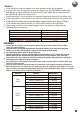
6 Adding refrigerant If the connecting pipe is longer than 7 metres, add refrigerant as needed. (Cool only type) added amount A=(Lm-7m) 15g/m ; (Heat pump type)added amount A= (Lm-7m) 50g/m. ( A: amount of added refrigerant, L: the length of connecting pipe) The length of connecting pipe (m) 7 8 9 10 (Cool only type)added amount (g) 0 15 30 45 (Heat pump type)added amount (g) 0 50 100 150 Exhaust the air as the above-mentioned method.