
User's Manual

31 May 2022
5 of 14
RED4S User’s Manuals
2 Operation Method
to HOST
UART TXD
UART RXD
J1
1
2
J3
CON3
1
2
3
(optional)
U2
VIN
1
EN
2
VOUT
3
to HOST
VCC=3.3V
LDO
ENABLE
V_battery
V_battery
SW1
1 2
When ENABLE is high, RED4S ON
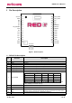
RED4S
U1
RED4S
VCC36
1
GND1
2
GND10
26
GND9
25
P00_RXD0
35
P01_TXD0
34
NC7
31
NC1
3
NC2
4
NC3
5
NC4
6
NC5
9
NC6
14
P12
13
NC9
33
NC8
32
GND2
15
GND3
16
GND4
17
RF I/O
18
GND5
19
VCC36P
20
VCC36P
21
GND6
22
GND7
23
P15
10
P16
11
ISP_MODE
7
P17
12
SWDIO
28
SWCLK
29
RESET
30
CSE
8
GND11
27
GND8
24
RF_IO
SWDIO
SWCLK
P00_RXD0
P01_TXD0
P16
P12
P15
P17
(optional)
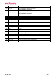
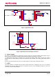
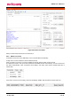
Figure 2 Application Circuit
(optional)
J1
BM24-10DP/2-0.35V
1
2
3
4
5
6
7
8
9
10
11
12
13
14
P01_TXD0
VCC36
VCC36
RESETb
P00_RXD0
ISP_MODEb
CSE
V_battery
VCC36P
SW1
1 2
U1
VIN
1
EN
2
VOUT
3
VCC=3.3V
ENABLE
V_battery
When ENABLE is high, RED4S ON
to HOST
UART RXD
UART TXD
P16
P15
P17
GND
GND
VCC36P
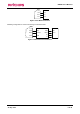
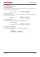
Figure 3 Application circuit: DC/Signal connector
2.1 Power Supply
DC power to operate RED4S is separated by 2 kinds. VCC36 is to supply for PR9200 which power range is
3.3 to 3.6 volts, VCC36P is to supply for power amp which power range is 3.3 to 4.2 volts.
In mobile device with battery, VCC36P can be connected to battery power directly. VCC36 pins need to
external LDO (or another device). As the Host control the LDO’s enable, user control power down mode of
module.
If you do not control external LDO, you can control CSE pin to enter power down mode instead.
2.2 UART
The serial interface is assigned with two wires. RXD0, which pin is assigned to pin 35, is for receiving
command from host and TXD0, which pin is assigned to pin 34, is for transmitting response to host. Pin
connection is shown as below figure.