Technische Dokumentation ITO-Key ITO-Key Technische Dokumentation Abbildung: Beispiel ITO-Key LNT Automation GmbH LNT_ITO-Key_techn_Doku_2016-12-12_V01_5.
Technische Dokumentation ITO-Key Inhalt 1 2 3 Einleitung ......................................................................................................................................... 3 1.1 Die perfekte Ergänzung für Ihren Touchscreen....................................................................... 3 1.2 Die Vorteile des kapazitiven Tasters ....................................................................................... 3 Lieferumfang ..........................................
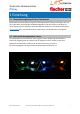
Technische Dokumentation ITO-Key 1 Einleitung 1.1 Die perfekte Ergänzung für Ihren Touchscreen Elektromechanische Einzeltaster ergänzen bisher Multitouch-Displays und steigern somit in den industriellen Anwendungen die Bedienmöglichkeit und den Komfort. Allerdings hat diese Lösung auch ihre bekannten Nachteile. Mit dem kapazitiven Einzeltaster ITO-Key der glass-to-touch Serie von LNT Automation GmbH lassen sich die Nachteile nun beheben. 1.
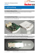
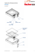
Technische Dokumentation ITO-Key 2 Lieferumfang Den ITO-Key gibt es in 3 verschiedenen Ausführungen: 2.1 Minimalausführung ITO-Key In der einfachsten Ausführung des ITO-Keys gibt es eine Sensorfläche im Grundkörper inklusive dem Backlight und der LED-Beleuchtung. 2.2 Standardausführung ITO-Key Die Standardvariante ist der ITO-Key mit der Sensorfläche im Grundkörper, dem Backlight inklusive der LED- Beleuchtung und der Auswertelektronik. Abbildung: Beispiel ITO-Key mit Sensorfläche +Backlight und inkl.
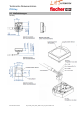
Technische Dokumentation ITO-Key 3 Übersicht 3.1 Aufbau des ITO-Key Der ITO-Key ist mit einer Klebeschicht zur einfachen Befestigung hinter einer Glasfront ausgestattet. Zur Ansteuerung der Hintergrundbeleuchtung sind zwei Kontakte aus dem Grundkörper herausgeführt. Zusätzlich befinden sich auf der Rückseite des ITO-Keys drei Anschlusspins für die kundeneigene Auswertelektronik. In der Standardausführung des ITO-Key kommt zu dem bestehenden Grundkörper eine Auswertelektronik.
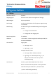
Technische Dokumentation ITO-Key 4 Eigenschaften 4.1 ITO-Key Auswertverfahren: kapazitiv Ausgangssignal: diskreter Taster (Alternative Signale auf Anfrage) Abmessungen: 26,5 x 20,8 x 9 mm Befestigung: Vorderseite selbstklebend (auf geeignete Zugentlastung ist zu achten) Beleuchtung: Die Ansteuerung der LED-Beleuchtung kann konfiguriert werden.
Technische Dokumentation ITO-Key Verpolungsschutz: vorhanden Handschuhbedienung: möglich Wassererkennung: auf Anfrage Temperaturbereich: -20°C bis +70°C (Arbeitstemperatur / Lagertemperatur) Reaktionszeiten : unter 5 ms möglich Spannungsversorgung: 5V - 30V+/- 5% (Standard) max 100mV Ripple / Stromaufnahme: Typ 10 mA bei 5V bis 11 V ohne LED Typ 5 mA bei 11V bis 30 V ohne LED Typ 25 mA mit LED EMV Beständigkeit: Störaussendung: EN 55014-1:2006 + A1:2009 +A2:2011 EN 55022:2010 Klasse B EN 6100
Technische Dokumentation ITO-Key 4.2 Maßzeichnungen ITO-Key: LNT Automation GmbH LNT_ITO-Key_techn_Doku_2016-12-12_V01_5.
Technische Dokumentation ITO-Key ITO-Sensor: LNT Automation GmbH LNT_ITO-Key_techn_Doku_2016-12-12_V01_5.
Technische Dokumentation ITO-Key 4.3 Anschlussbelegung Steckerbelegung ITO-Key: Pin 1 2 3 4 Name Versorgung Eingang LED GND Ausgang Funktion Betriebsspannung Eingang LED Beleuchtung (konfigurierbar) Masse Ausgang Taster/Schalter Steckerbelegung ITO-Sensor: Pin A (+) K (-) 1 2 3 Name Anode Kathode ITO-Sensorfläche 1 ITO-Sensorfläche 2 ITO-Sensorfläche 3 Funktion Anschluss Pluspol Anschluss Minuspol Taste (Zentraler Punkt) Guard (innerer Ring) Shield (äußerer Ring) 4.
Technische Dokumentation ITO-Key 5 Optionen 5.1 Typenbezeichnung IK WS Artikelnummer Firmware S Bezeichnung IK = *Firmware ITO-Key IK = ITO-Key IS= ITO-Sensor V 0.10.
Technische Dokumentation ITO-Key 6 Konfiguration 6.1 Konfigurationsübersicht Die ITO-Keys lassen sich mit Hilfe einer zusätzlichen erhältlichen Software und einem optional erhältlichen Kabel auch programmieren.
Technische Dokumentation ITO-Key 6.3 Konfigurationshardware Zur Konfiguration der ITO-Keys ist ein zusätzliches Kabel (Konfigurationskabel) notwendig. Dieses Kabel ist optional bei uns erhältlich. Artikelnummer: 302721 6.4 Maßzeichnung Konfigurationskabel 6.5 Anschlussbelegung Konfigurationskabel FTDI-Kabel: Connector PHR-4 Pin 1 Pin 2 Pin 3 Pin 4 LNT Automation GmbH Kabelfarbe rot orange schwarz gelb Signal UB+ Input_LED (TX) GND OUT (RX) LNT_ITO-Key_techn_Doku_2016-12-12_V01_5.
Technische Dokumentation ITO-Key 7 Info 7.1 Rücknahme Elektroschrott Die Rücknahme von Altgeräten (Elektroschrott) zur sicheren Entsorgung nach dem Elektro- und Elektronikgerätegesetzt (ElektroG) wird vom Hersteller gewährleistet 7.2 Datenblatt Historie Version V 01.0 V01.1 V01.2 V01.3 V01.4 V01.
Technische Dokumentation ITO-Key 7.3 Hinweis Die gelieferte Hardware darf nicht in lebenserhaltenden Geräten oder Systemen eingesetzt oder dazu verwendet werden. Gleiches gilt für Geräte oder Systeme, die extremen Umweltbelastungen/Einflüssen ausgesetzt sind oder direkte Gefahrenquellen für Leben jeglicher Art darstellen. Dokument REV. 2016-12-12-V 01.5-DE Änderungen und Irrtümer bleiben vorbehalten. Bilder und sonstige Grafiken sind nur Beispiele. Weitere Informationen unter: www.glasstotouch.de www.