
User's Manual


12
12
The GS375 System
The GS375 System
4.2
4.2
Replacing the Sensor
Replacing the Sensor
Antenna
Antenna
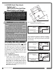
Heavily damaged antennas (ripped out, sheared off,
wire exposed and fraying etc.) should be replaced to
ensure effective communication between the sensor
and the cabin mounted display unit.
This procedure may be followed without removing
the sensor from the crane if it is safe to do so.
1. Place the crane, boom, jib or ball hook such that
the sensor is safely accessible.
2. Clean dust, grime and water from the sensor.
3. Identify the short black whip antenna and the
white hex bolt securing it.
4. Inspect the antenna for signs of obvious
physical damage.
5. Carefully unscrew the white nylon hex bolt
completely and slide it up the antenna.
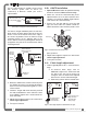
6. Grip the antenna by the base of the black
plastic sheathing and pull it straight out of the
hole in which it is seated. Place the old antenna
aside.
7. Slide the white nylon hex bolt to the middle of
the length of the new antenna.
8. Coat the exposed metal foot of the new antenna
with an electrical insulating compound by
carefully inserting it in the mouth of the
compound tube.
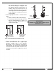
9. Hold the new antenna by the black plastic
sheathing and guide it through the hole in the
sensor box. Carefully seat the antenna in its
mating connector. When the antenna is
correctly seated, pulling on it will be met with
light resistance.
10.Carefully re-thread, screw-in and tighten the
white nylon hex bolt to secure the antenna in
place. Do not overtighten.
11. Reinstall the sensor if necessary.
12.Verify that the sensor functions properly.
GS050 GS075
5
5
7/16 in.
wrench
7/16 in.
wrench
Figure: Unscrew the white nylon hex
6
6
GS050 GS075
Figure: Pull out the antenna
8
Electrical insulating
compound
Figure: Coat the exposed metal foot of the antenna
White nylon hex bolt
TA011 Antenna
Sensor box
Antenna receptacle
Figure: Install the new antenna
IMPORTANT!
The interior of the sensor
must be protected from dust, grime and
water at all times.
!
!