
User's Manual Part 1


ITRODUCTIO
ITRODUCTIO
5
5
1.1
1.1
Overview
Overview
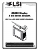
The GS820 system includes the cabin mounted
GS820 radio display and compatible crane
mounted sensors. The GS820 creates a two-way
radio network with the sensors to bring required lift
data to the operator. Hoist load, boom and jib
angles, boom length, wind speed and pending two-
block can be detected and then indicated to the
operator in real time. Working load radius can be
calculated and compared to a rated capacity chart
(if programmed). Furthermore the GS820 can be
programmed to generate warnings, alarms and
lockout commands, all triggered by adjustable
thresholds and limits. All these events can be
recorded by the data logger with a time and date
stamp. The exact operational function of the
GS820 system depends on the sensor
configuration used and the rated capacity charts
programmed (where applicable). The GS820
includes a USB port to facilitate software and chart
updates and data logger downloads using a USB
mass storage device (USB key).
1.2
1.2
Start-Up
Start-Up
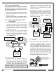
The GS820 must be correctly programmed for the
system sensors installed. Once a reliable radio
communication network is established, the display
lights will remain lit without flashing. If a sensor is
missing or has a problem, a message will be
displayed on the LCD (liquid crystal display).
This process may take up to one minute. The delay
is created by the battery management function.
Press Bypass/Exit to temporarily bypass crane
function lockout caused by a missing sensor. If
rigging requires a crane configuration outside of the
limits defined by the rated capacity chart selected,
out of chart alarms can be avoided by placing the
the display in "rig mode". If the rig mode is enabled
in the display, press Bypass/Exit for 10 seconds
to activate it. If the rig mode is not available, contact
your
LSI
LSI representative or
LSI
LSI technical support
representative.
1.
1.
INTRODUCTION
INTRODUCTION
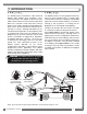
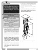
GS050 Anti-Two-
Block Switch
GS075 All-In-One
Anti-Two-Block
Switch and weight
GS101 Angle and
Length Sensor
GS820 Display
GC Series
Load Cell
Figure: Key components in a typical system installation. Your product may vary. Not to scale.
WARNING!
The GS820 system is designed
as an operator aid and is in no way a
substitute for safe operating practice.
!
!