
User's Manual Part 1


ISTALLATIO
ISTALLATIO
7
7
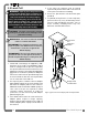
2.1b Antenna Position
For optimal performance the antenna should be
positioned on its side such that it is parallel to
the sensor antennas (but not pointing directly to or
directly away from them).
1. Adjust the antenna position with the articulating base.
2. The antenna should have 5 inches of clear
space all around it.
3. The antenna should have an unobstructed line of
sight to all sensor antennas at all boom angles.
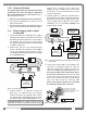
2.1c Power Supply and Lockout
Connection
1. Connect the black wire (ground) to the negative
terminal of the battery or the panel connection;
alternatively bolt the black wire to the body of
the machine with a 1/4 inch or 5/16 inch bolt.
The ground connection must be strong enough
to sustain 3 amperes.
2. Connect the red wire to a fused accessory
source, rated at least 3 amperes, that supplies
+12 or +24 volts when the machine is in use.
The GS820 will automatically detect the voltage
level and adjust itself.
3. Lockout number 1 (if required): connect the
white wire to a Bosch relay coil terminal.
Connect the other coil terminal of the relay to
the ground. When operating properly the white
wire will energize at the battery positive level.
Current over 1 ampere on the white wire
triggers an auto re-settable fuse. Current flow
will resume several seconds after the short
circuit is eliminated.
4. Lockout number 2, 3 and 4 (if required): these
wires function in the same way as the white wire
described in step 3 above. Each lockout wire
can be triggered by a different set of alarm
conditions; see the Lockout Settings sub
section of this manual.
5. Connect the yellow cable to the GS820. The
connector is waterproof and well rated for
external environments. Simply connect the
cable to the display and gently tighten the nut.
Do not put a kink in the yellow cable where
it enters the connector; any bend in the cable
at the base of the connector must not be so
severe as to break the internal connections
where the cable meets the connector. The
power cable requires about 4 1/2 in. behind
the display to protect the connector.
Power Supply
or Battery
+12 V or +24 V
Black
wire
Red wire
White wire
Orange wire
Green wire
Blue wire
Lockout #1
Lockout #2
Lockout #3
Lockout #4
Yellow cable
To GS820 power supply
connector (Step 5)
n.c.
n.o.
co
Power Supply
or Battery
+12 V or +24 V
Black
wire
Red wire
White wire
Orange wire
Green wire
Blue wire
Lockout #1
Lockout #2
Lockout #3
Lockout #4 - Optional
To valve coil if
normally open is
required
Yellow cable
To valve coil if
normally closed
is required
Bosch relay
Yellow cable
Black wire: Negative (ground)
Red wire: Positive 12 or 24 volts
White wire: Lockout #1
Orange wire: Lockout #3
Green wire: Lockout #2
Blue wire: Lockout #4
Figure: Connection without lockout.
Figure: Connection with white wire lockout and recommended
Bosch relay.
Figure: GS820 power supply connector
Troubleshooting: if no voltage is present on the
white wire remove the load connected to the lockout.