
User's Manual Part 1


8
8
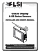
The GS820 System
The GS820 System
2.1d Lockout Settings
Warning, alarm and lockout control is programmed
in this menu. The GS820 can be programmed to
generate alarms and lockouts for almost all
programmed limits and two-block. Furthermore,
warnings are generated when approaching
programmed load limits and rated capacity (when
applicable).
Warning level. When gross load (regardless of
tare value) approaches the maximum limit for a
load sensor, an intermittent warning message is
generated on the LCD. The maximum limit for a
load sensor is the lower of; a) the operator set limit
(Limit Menu), and b) the working load limit (WLL) if
rated capacity charts are used. The proportion of a
limit that must be reached to trigger the overload
warning is the warning level. The default factory
setting for the warning level is 90%.
1. Go to menu 4G) L
OCKOUT SETTINGS.
2. Enter the user password (using Back, Next, Up
and Down as described in Password settings
section) and press Enter.
3. Select 1) W
ARNING LEVEL and press Enter to
modify.
4. Use Up and Down to adjust the warning level
and press Enter to confirm any change.
3. Press Down to select 2) A
LARM LEVEL or press
Exit to return to the operation display.
Alarm level. All programmed and rated capacity
limits and two-block will generate an audible alarm
when the alarm level is reached. Alarms will
generate an intermittent alarm message on the
LCD. The proportion of a limit that must be reached
to trigger an alarm is the alarm level. The default
factory setting for the alarm level is 100%.
1. In menu 4G), select 2) A
LARM LEVEL and press
Enter to modify.
2. Use Up and Down to adjust the alarm level and
press Enter to confirm any change.
3. Press Down to select 3)
LOCKOUT LEVEL or press
Exit to return to the operation display.
Lockout level. All programmed and rated capacity
limits and two-block can generate a lockout signal
when the lockout level is reached. By default the
lockout wires carry crane power supply voltage as
long as the display is in safe condition (to inverse
lockout polarity see menu 4G) 8) L
OCKOUT RELAY
INVERTED). When a lockout level is reached voltage
is cut on all lockout wires linked to the lockout
condition (see menu 4G) 4) through 4G) 7)). The
proportion of a limit that must be reached to trigger
lockout is the lockout level. The default factory
setting for the lockout level is 105%.
1. In menu 4G), select 3) L
OCKOUT LEVEL and press
Enter to modify.
2. Use Up and Down to adjust the lockout level
and press Enter to confirm any change.
3. Press Down to select 4)
WHITE WIRE LOCKOUT
TRIGGER or press Exit to return to the operation
display.
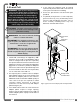
Lockout triggers. Different events can be
programmed to cut voltage on the lockout wires of
the yellow cable. Each lockout wire can be linked to
a different combination of lockout conditions.
1. In menu 4G), select 4) W
HITE WIRE LOCKOUT
TRIGGER and press Enter to modify.
2. Select which alarm conditions will trigger
lockout on the white wire (see tables below).
3. Add the lockout codes for the selected alarms
together to find the lockout trigger number.
4. Use Up and Down to adjust the white wire
lockout trigger number and press Enter to
confirm any change.
5. Press Down to select the next wire trigger line
and repeat steps 1 through 5, or, press Exit to
return to the operation display.
Table: Default Triggers
Lockout Wire Default Trigger
White . . . . . . . . . . . . . . . . . . . . . . . . . . . . 4301
Green . . . . . . . . . . . . . . . . . . . . . . . . . . . . . . 34
Orange . . . . . . . . . . . . . . . . . . . . . . . . . . 32767
Table: Lockout Codes
Condition Code
Maximum wind speed . . . . . . . . . . . . . . . . . . 1
Minimum angle. . . . . . . . . . . . . . . . . . . . . . . . 2
Maximum angle . . . . . . . . . . . . . . . . . . . . . . . 4
Overload . . . . . . . . . . . . . . . . . . . . . . . . . . . . 8
Not used. . . . . . . . . . . . . . . . . . . . . . . . . . . . 16
Maximum radius. . . . . . . . . . . . . . . . . . . . . . 32
Maximum length. . . . . . . . . . . . . . . . . . . . . . 64
Two-block. . . . . . . . . . . . . . . . . . . . . . . . . . 128
Maximum wind gust . . . . . . . . . . . . . . . . . . 256
Maximum rope payout . . . . . . . . . . . . . . . . 512
Minimum slew . . . . . . . . . . . . . . . . . . . . . 1024
Maximum slew . . . . . . . . . . . . . . . . . . . . . 2048
Maximum tip height . . . . . . . . . . . . . . . . . 4096
Maximum imbalance factor . . . . . . . . . . . 8192