
User guide

96
www.loadstarsensors.com • sales@loadstarsensors.com • Specifi cations subject to change without notice.
© 2014 Loadstar Sensors • 48521 Warm Springs Blvd., Suite 308, Fremont, CA 94539 • P: (510) 274-1-USB or (510) 274-1872 F: (510) 952-3700
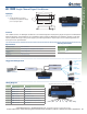
AI-1000 Single Channel Signal Conditioner
Highlights
Technology
ì Accepts standard mV/V signals
and outputs an amplifi ed DC voltage
(0.5—4.5V) signal output
Specifi cations
Load Cell Connector
Screw Terminal Block
Power
Operating Voltage 8–30V DC regulated or filtered unregulated
Operating Current
5mA, plus bridge current
Excitation
5V
Bridge Input
Full Wheatstone Bridge
Overview
The Loadstar Sensors’ AI-1000 Signal Conditioner is an interface designed to amplify strain gauges arranged in a full Wheatstone
bridge confi guration, and is suitable for many applications where a bridge or differential input amplifi er is required. The AI-1000
may be operated with single or dual power supply to provided singed-ended or bipolar output, and includes bridge offset and
circuit gain trimmer potentiometers.
3.80
1.00
.12
.89
.12
3.24
1.40
4.20
4X R.20
4X
.19 THRU
AI-1000
Resistive Load Cell
Suggested Confi guration
Wiring Diagram
Power
Load Cell
Programmable
Logic
Controller
Digital
Multi Meter
Indicator
Data
Acquisition
Output
Ordering Information
Available Con gurations
Option Part No.
Basic
AI-1000
Position Signal Name Description
1
Load Cell: +Excitation
Color Code: Red
2
Load Cell: -Excitation
Color Code: Black
3
Load Cell: +Signal
Color Code: Green
4
Load Cell: -Signal
Color Code: White
5
AI-1000: +VDC Output
Output: 0.5VDC – 4.5VDC
6
AI-1000: +Power Input
Power adatper (Positive; with white stripe)
7
AI-1000: -Power Intput
Power adapter (Negative; merged with ground)
8
AI-1000: -VDC Output
Output: Ground
1 2 4 5 6 7 83
The picture (above) shows the port/position of the AI-1000.
Load Cells
•
Resistive