
Instructions / Assembly


Installation & Assembly Instructions
Please contact our Customer Service Division with any questions at:
30700 D Carter Street ∙ Solon, OH 44139 ∙ (P) 440.248.5480 ∙ support@tritonproducts.com
For a full line of products visit www.tritonproducts.com 1 INLBD2114
Read all instructions completely before installing. Should you have any questions about your installation, please
call Customer Service at 440-248-5480
Inventory and inspect all components before starting assembly (Use figure 1-1 page 3)
Report Any Missing Parts and/or Damaged Goods within 5 Days from Receipt
QTY Description
(1) Stainless Steel Bottom Tray
(2) Left Hand Stainless Steel Corner Angle brackets
(1) Right Hand Stainless Steel Corner Angle Bracket with 4 holes for handle attachment
(1) Right Hand Stainless Steel Corner Angle Bracket without holes for handle attachment
(2) Rail End Brackets interchangeable (Triangular with 4 preinstalled threaded fasteners)
(1) Top Rail (48” Long)
(1) Cart Handle
(2) Fixed Casters
(2) Swivel Casters
(4) Stainless Steel LocBoard Pegboard w/ square holes 24” X 42.5”
(28) 1/4"-20 X 3/4” Truss Head Bolts (16 for casters, 8 for rail end brackets, 4 for outside of uprights)
(12) 1/4"-20 x 1/2" Tapered Phillips flat head screws. (4 For Handle Attachment, 8 for inside of uprights
where boards attach.)
(26) 12-24X 1/4" Socket Head Cap Screws (For Attachment of LocBoards.)
(16) Flat Washers for Casters
(16) ¼” Locknut
Note: While attaching components it’s important to remember not to fully tighten any bolt until system is fully
assembled. Freedom of movement will allow for proper alignment between bolts and their associated preinstalled
threaded fasteners. Tapered Flat head screws with under-cut head used for attachment of corner angle brackets on
the FRONT edge will be tightened just before installation of LocBoards. For assembly purposes the END will always be
the narrowest dimension of cart.
Assembly:
1. Locate the (4) corner angle brackets. Using Parts Call-Out figure 1-1 page 3, identify the left from the right
brackets and their top edge from their bottom edge. The top’s edge can be identified by the angle cut into
each bracket and its 2-top bolt mounting holes when looking from the END view.
2. Position the bottom tray with the lip facing up and one end facing you. Special Note: the end of the bottom
tray with caster mounting holes pattern running parallel to the end lip will be the end that you will mount
swivel casters and right-hand angle bracket with pull handle.
3. (Refer to Figure 2-1, 2-2 and 2-3) Note: All corner angle brackets will install outside of the bottom tray lip.
Starting with a left corner angle bracket and using 1/4"-20 X 3/4” Truss Head Bolts align bottom bolt hole in
angle bracket with pre-installed threaded fastener on the left end of bottom tray and insert bolt with hand
tighten (Do Not Tighten All The Way). From the front edge of the same angle bracket install a 1/4"-20 x 1/2"
Tapered Phillips flat head screw. (Repeat step #3 for each corner bracket.)
4. (Refer to Figure 1-1, 2-1 and 2-4) Installing Top Rail: Top rail will be positioned inside both sets of installed
corner angle brackets at each end. From the front edge install 1/4"-20 x 1/2" Tapered Phillips flat head screws
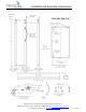
LBC-4SS - Stainless Steel 48” L x 46” H x 26-5/8” W LocBoard® Tool Cart with Stainless Steel
Frame