SM-PCPII Rev B PC PROGRAM INSTRUCTIONS Models: Knight, Knight XL, Knight Wall Mount, Knight Wall Hung and Armor WARNING This manual must only be used by a qualified heating installer / service technician. Read all instructions, including this manual, the Installation and Operation Manuals, and the Service Manuals, before installing. Perform steps in the order given. Failure to comply could result in severe personal injury, death, or substantial property damage. Save this manual for future reference.
Contents 1. INSTALLATION Program Installation ..................................................... USB Installation ........................................................... Program Setup ............................................................ Starting the Program ................................................... 2. SMART SYSTEM Status Screen ................................ 3. SMART SYSTEM Graphics Screen ............................ 4. SMART SYSTEM Data Logging Screen ..................... 5.
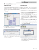
PC Program Instructions 1 Installation (continued) USB installation Program setup Your PC will communicate with the SMART SYSTEM control through the USB cable included with the kit. This communication will require a specific USB driver. This driver may be installed by starting the SMART SYSTEM PC program. To complete the USB installation, follow the steps below: The PC will assign a ComPort number to your SMART SYSTEM control connection.
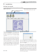
PC Program Instructions 1 Installation Starting the program To start the program, double click on the icon you placed on your desktop. Figure 1-1_Main Screen START COMMUNCATIONS ICON Note: On initial Startup the “round” command buttons should sequence from left to right. KEYS BUTTON Once opened and the appropriate Comport is selected, click on the “Start Communications” icon (using the double computer icon shown in FIG. 1-1) to begin communication.
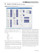
PC Program Instructions 2 SMART SYSTEM Status screen Figure 2-1_SMART SYSTEM Status Screen To monitor the operation of the heater, click on the Status tab along the top of the Main Screen window (FIG. 1-1, page 4). The Status Screen will appear (see FIG. 2-1 above).
PC Program Instructions 2 SMART SYSTEM Status screen Below the Sensors section is the Inputs section (FIG. 2-1, page 5). This section displays the status of each Enable (Loop Thermostat) Input, HW Thermostat, 0 - 10V System Pump Input, Louver Proving Switch (optional), Flow Switch / Low Water Cutoff (optional), Gas Pressure Switch (optional), Air Pressure Switch, and Blocked Drain Switch. Next to the Inputs section is the Outputs section (FIG. 2-1).
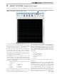
PC Program Instructions 3 SMART SYSTEM Graphics screen To access the Graphics Screen, click on the Graphics button along the top of the Main Screen window (FIG. 1-1, page 4). Figure 3-1_SMART SYSTEM Graphics Screen To observe the changes in various readings while the heater operates, click on the Graphics tab along the top of the Main Screen window (FIG. 1-1 on page 4). The SMART SYSTEM Graphics Screen will then appear (see FIG. 3-1 above).
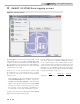
PC Program Instructions 4 SMART SYSTEM Data logging screen Figure 4-1_File Menu Screen By clicking File to access the drop down menu (FIG. 4-1), all logging functions are now accessible. Click Start Log or F10 to select a Save As location and File Name for the WinPro log file. If logging for a short period of time, click Stop Log or Shift+F10 when all of the desired data is acquired. This will complete and save the log file.
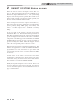
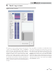
PC Program Instructions 5 Fault Log screen Figure 5-1_Fault Log Screen The Fault Log Screen provides historical data about the operation of the SMART SYSTEM. Click on the Fault Log tab along the top of the Main Screen window (FIG. 1-1, page 4). A window will appear with the status of numerous counters and lists of the most recent events (FIG. 5-1 above). Included are details of the control board serial number, software version, default parameters, production date, and last service date.
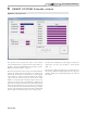
PC Program Instructions 6 SMART SYSTEM Cascade screen Figure 6-1_Cascade Screen The Cascade Screen provides the status of the Cascade system. The PC must be connected to the Leader (address 0) appliance. Click on the Cascade button along the top of the Main Screen window (FIG. 1-1, page 4). The Cascade System area shows the power demand and the setpoint, the boiler status, and the priority of each heater in the Cascade.
PC Program Instructions 7 SMART SYSTEM parameters By accessing the Parameter Screen, the installer can view all of the SMART SYSTEM parameters. The installer can also change certain specific parameters to fine tune the operation of the heater to the installation. To access the parameter list, click on the Parameters button along the top of the Main Screen window (FIG. 1-1, page 4). The parameters in the SMART SYSTEM will automatically upload to the PC software once opened.
PC Program Instructions 7 SMART SYSTEM parameters Figure 7-2_Parameters Min-Max Adjustment Screen Once adjustments to the parameters are complete, the values can be sent by pressing the Download button in the top section of the screen (FIG. 7-2). This will transfer the new parameters into the SMART SYSTEM. While the programming is taking place the appliance control will force a Post Purge Cycle through the combustion system as a reset function.
PC Program Instructions 8 Screenshots - parameter tables Figure 8-1_Non-adjustable Parameters Screen 13
PC Program Instructions 8 Screenshots - parameter tables Figure 8-2_General Parameters Screen 14
PC Program Instructions 8 Screenshots - parameter tables (continued) Figure 8-3_Temperature Settings Parameters Screen Figure 8-4_Functions Parameters Screen 15
PC Program Instructions 8 Screenshots - parameter tables Figure 8-5_DHW Settings Parameters Screen Figure 8-6_ Outdoor Reset Parameters Screen 16
PC Program Instructions 8 Screenshots - parameter tables (continued) Figure 8-7_Anti-Cycling Parameters Screen Figure 8-8_Control Modes Parameters Screen 17
PC Program Instructions 8 Screenshots - parameter tables Figure 8-9_Circulation Pumps Parameters Screen Figure 8-10_BMS Parameters Screen 18
PC Program Instructions 8 Screenshots - parameter tables (continued) Figure 8-11_Service Notification Parameters Screen 19
Revision A - (ECO #C07337) Initial release. Revision B (ECO C11568) reflects the update of the SMART SYSTEM logo on the manual cover.