
Smart System User Guide

2 SMART SYSTEM Status screen
6
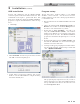
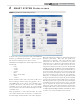
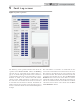
Below the Sensors section is the Inputs section (FIG. 2-1,
page 5). This section displays the status of each Enable (Loop
Thermostat) Input, HW Thermostat, 0 - 10V System Pump
Input, Louver Proving Switch (optional), Flow Switch / Low
Water Cutoff (optional), Gas Pressure Switch (optional), Air
Pressure Switch, and Blocked Drain Switch.
Next to the Inputs section is the Outputs section (FIG. 2-1).
This section shows the status of the Boiler (secondary) Pump,
System (primary) Pump, DHW pump, Louver Relay, Gas
Valve, 0 - 10V Rate Output, and 0 - 10V Boiler (secondary)
Pump.
At the top right of the window is the Fan Speed Status
information (FIG. 2-1). Included in the Fan Speed Status are
Min., Max., and Ignition fan speeds. The target and actual fan
speeds are displayed at the bottom of this section. Should the
temperature or the flame approach certain limits, the SMART
SYSTEM will force the fan speed up or down accordingly to
prevent exceeding those limits. When this happens, the box
next to the corresponding sensor is shown as “active”.
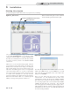
Below the Fan Speed Status is the Boiler Configuration. This
indicates the application to which the SMART SYSTEM is
programmed to be used (water heater or space heater with
optional tank), and the source of control (thermostat, BMS,
or Cascade).
General Status of the boiler is shown below the Boiler
Configuration. Included in the General Status is the active
call for heat (if any), the burner status, the last fault, and the
date and time as stored in the SMART SYSTEM.
Finally, the Log File navigation tools are shown. These tools
are used to navigate a previously stored log file. To learn how
to create and load a log file see Section 4, File Menu Screen on
page 8 of this manual.
PC Program Instructions