SYNC-I-O Rev F Installation & Operation Manual Models: 1.0 - 1.3 - 1.5 WARNING This manual must only be used by a qualified heating installer / service technician. Read all instructions, including this manual and the SYNC Service Manual, before installing. Perform steps in the order given. Failure to comply could result in severe personal injury, death, or substantial property damage. Save this manual for future reference.
Contents HAZARD DEFINITIONS . . . . . . . . . . . . . . . . . . . . . . . . . . 2 PLEASE READ BEFORE PROCEEDING . . . . . . . . . . . . 3 THE SYNC -- HOW IT WORKS . . . . . . . . . . . . . . . . . . . . 4-5 RATINGS . . . . . . . . . . . . . . . . . . . . . . . . . . . . . . . . . . . . . . 6 1. DETERMINE BOILER LOCATION Closet and Alcove Installations . . . . . . . . . . . . . . . . . . . . . 7 Provide Air Openings to Room . . . . . . . . . . . . . . . . . . . . . 9 Flooring and Foundation . . . . . . . . .
Installation & Operation Manual Please read before proceeding WARNING Installer – Read all instructions, including this manual and the SYNC Service Manual, before installing. Perform steps in the order given. User – This manual is for use only by a qualified heating installer/service technician. Refer to the User’s Information Manual for your reference. NOTICE • To avoid electric shock, disconnect electrical supply before performing maintenance.
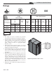
Installation & Operation Manual The SYNC - How it works... 1. Access cover - front Provides access to the gas train and the heat exchanger. 2. Air intake adapter Allows for the connection of the PVC air intake pipe to the boiler. 3. Air pressure switches 4. Air shrouds (1.0 Model only) The air pressure switches detect blocked flue/vent conditions. The air shrouds control air and gas flow into the burners. 5. 6. 23. Heat exchanger access covers Allows access exchanger coils.
Installation & Operation Manual The SYNC - How it works... (continued) Models 1.0 - 1.3 - 1.5 12 40 42 30 34 3 17 31 13 27 28 18 19 16 21 1 38 Front View Rear View 35 11 4 1.
Installation & Operation Manual Ratings SYNC I=B=R Rating Input MBH Model Number Note: Change “N” to “L” for L.P. gas models. (Note 4) Other Specifications Gross Output MBH Net I=B=R Ratings Water, MBH Appliance Water Content Gallons Outlet Water Inlet Water Gas Connections Air Vent Size Size Min Max (Note 1) (Note 2) SBN1000 100 1000 941 818 8.4 2½" (2) - 2" 1½" 6" 6" SBN1300 130 1300 1237 1076 10.0 2½" (2) - 2" 1½" 6" 6" SBN1500 150 1500 1444 1256 11.
Installation & Operation Manual 1 Determine boiler location Installation must comply with: • Local, state, provincial, and national codes, laws, regulations, and ordinances. • National Fuel Gas Code, ANSI Z223.1 – latest edition. • Standard for Controls and Safety Devices for Automatically Fired Boilers, ANSI/ASME CSD-1, when required. • National Electrical Code. • For Canada only: B149.1 Installation Code, CSA C22.1 Canadian Electrical Code Part 1 and any local codes. NOTICE 2. 3.
Installation & Operation Manual 1 Determine boiler location Figure 1-1 Closet Installation - Minimum Required Clearances 1" (25 MM) MINIMUM CLEARANCE AROUND HOT WATER PIPES AND VENT PIPE WARNING For closet installations, CPVC or stainless steel material MUST BE used in a closet structure due to elevated temperatures. Failure to follow this warning could result in fire, personal injury, or death.
Installation & Operation Manual 1 Determine boiler location (continued) Provide air openings to room: Vent and air piping The SYNC alone in boiler room The SYNC requires a special vent system, designed for pressurized venting. 1. No air ventilation openings into the boiler room are needed when clearances around the SYNC are at least equal to the SERVICE clearances shown in FIG.’s 1-1 and 1-2. For spaces that do NOT supply this clearance, provide two openings as shown in FIG. 1-1.
Installation & Operation Manual 1 Determine boiler location When using an existing vent system to install a new boiler: WARNING Failure to follow all instructions can result in flue gas spillage and carbon monoxide emissions, causing severe personal injury or death.
Installation & Operation Manual 1 Determine boiler location When removing a boiler from existing common vent system: DANGER Do not install the SYNC into a common vent with any other appliance. This will cause flue gas spillage or appliance malfunction, resulting in possible severe personal injury, death, or substantial property damage. WARNING Failure to follow all instructions can result in flue gas spillage and carbon monoxide emissions, causing severe personal injury or death.
Installation & Operation Manual 1 Determine boiler location Combustion and ventilation air requirements for appliances drawing air from the equipment room Provisions for combustion and ventilation air must be in accordance with Air for Combustion and Ventilation, of the latest edition of the National Fuel Gas Code, ANSI Z223.1, in Canada, the latest edition of CGA Standard B149 Installation Code for Gas Burning Appliances and Equipment, or applicable provisions of the local building codes.
Installation & Operation Manual 1 Determine boiler location (continued) Where two openings are provided, one must be within 12" (30cm) of the ceiling and one must be within 12" (30cm) of the floor of the equipment room. Each opening must have net free area as specified in the chart below (Table 1B). Single openings shall commence within 12" (30cm) of the ceiling. CAUTION Figure 1-7_Combustion Air from Outside - Single Opening 4.
Installation & Operation Manual 2 General venting Direct venting options - Sidewall Vent PVC/CPVC Two Pipe See Figure 3-1A Stainless Steel Two Pipe See Figure 3-2 Sidewall Vent Optional Room Air PVC/CPVC Room Air See Figure 4-5 14 Stainless Steel Room Air See Figure 4-5
Installation & Operation Manual 2 General venting (continued) Direct venting options - Vertical Vent PVC/CPVC Two Pipe See Figure 4-1 Stainless Steel Two Pipe See Figure 4-2 Vertical Vent Optional Room Air PVC/CPVC Room Air See Figure 4-5 Stainless Steel Room Air See Figure 4-5 15
Installation & Operation Manual 2 General venting Direct venting options - Vertical Vent, Sidewall Air PVC/CPVC Vertical Vent, Sidewall Air Stainless Steel Vertical Vent, Sidewall Air 16
Installation & Operation Manual 2 General venting (continued) Install vent and combustion air piping DANGER The SYNC must be vented and supplied with combustion and ventilation air as described in this section. Ensure the vent and air piping and the combustion air supply comply with these instructions regarding vent system, air system, and combustion air quality. See also Section 1 of this manual.
Installation & Operation Manual 2 General venting PVC/CPVC air intake/vent connections 1. Combustion Air Intake Connector (FIG. 2-2) - Used to provide combustion air directly to the unit from outdoors. A fitting is provided on the unit for final connection. Combustion air piping must be supported per guidelines listed in the National Mechanical Code, Section 305, Table 305.4 or as local codes dictate. 2. Vent Connector (FIG.
Installation & Operation Manual 2 General venting (continued) Requirements for installation in Canada 1. 2. 3. Installations must be made with a vent pipe system certified to ULC-S636. IPEX is an approved vent manufacturer in Canada supplying vent material listed to ULC-S636. The first three (3) feet of plastic vent pipe from the appliance flue outlet must be readily accessible for visual inspection.
Installation & Operation Manual 2 General venting When a sidewall or vertical rooftop combustion air supply system is disconnected for any reason, the air inlet pipe must be resealed to ensure that combustion air will be free of contaminants and supplied in proper volume. DANGER Failure to properly seal all joints and seams as required in the air inlet piping may result in flue gas recirculation, spillage of flue products and carbon monoxide emissions causing severe personal injury or death.
Installation & Operation Manual 2 General venting (continued) Table 2C Direct Vent Minimum / Maximum Allowable Air / Vent Lengths Vent Diameter Vent Min. Length Vent Max. Length Input De-Rate per 25 feet of Vent 100' 50' 6" 6" 12' 12' 100' 50' 1.25% 2.90% 12' 100' 7" 12' 100' 0.95% 12' 50' 6" 12' 50' 3.30% 12' 100' 7" 12' 100' 1.65% Model Air Intake Diameter Air Intake Air Intake Min. Length Max.
Installation & Operation Manual 3 Sidewall direct venting Vent/air termination – sidewall WARNING Follow instructions below when determining vent location to avoid possibility of severe personal injury, death, or substantial property damage. A gas vent extending through an exterior WARNING wall shall not terminate adjacent to a wall or below building extensions such as eaves, parapets, balconies, or decks.
Installation & Operation Manual 3 Sidewall direct venting (continued) Vent/air termination – sidewall Figure 3-2A Clearance to Gravity Air Inlets Figure 3-1C Alternate Stainless Steel Sidewall Termination w/Field Supplied Fittings NOTICE PVC/CPVC or ABS is acceptable air inlet pipe material. 12" MIN. TO BOILER INTAKE AIR CONNECTION VENT / AIR TERMINATION 12" MIN. 12" (305 MM) MIN 15" (381 MM) MAX FROM BOILER VENT PIPE CONNECTION 12" (305 MM) MIN 12" MIN.
Installation & Operation Manual 3 Sidewall direct venting Figure 3-3B Alternate Clearance to Forced Air Inlets Figure 3-4A Sidewall Termination Assembly (PVC/CPVC) w/Field Supplied Fittings IF LESS THAN 10’ (3 M) AIR PIPING VENT PIPING 36” (914 MM) MIN VENT PLATE WALL PLATE VENT CAP GALVANIZED THIMBLE FORCED AIR INLET BIRD SCREEN (TYPICAL) 7’ (2.1 M) MIN ABOVE ANY PUBLIC WALKWAY Prepare wall penetrations (Alternate Field Supplied Options) 1. Prepare wall penetrations 1. 2. 3. 4. 5.
Installation & Operation Manual 3 Sidewall direct venting (continued) Termination and fittings 1. The air termination coupling must be oriented at least 12 inches above grade or snow line as shown in FIG. 3-1A, page 22. 2. Maintain the required dimensions of the finished termination piping as shown in FIG. 3-1A, page 22. 3. If using a stainless steel sidewall termination do not extend exposed vent pipe outside of the building more than what is shown in this document.
Installation & Operation Manual 4 Vertical direct venting Vent/air termination – vertical WARNING WARNING NOTICE Follow instructions below when determining vent location to avoid possibility of severe personal injury, death or substantial property damage. ALTERNATE INTAKE LOCATIONS: INTAKE PIPES MAY BE LOCATED ANYWHERE WITHIN 24” (610 MM) OF VENT PIPE Do not connect any other appliance to the vent pipe or multiple boilers to a common vent pipe.
Installation & Operation Manual 4 Vertical direct venting (continued) 3. The vent piping must terminate in an up-turned coupling as shown in FIG. 4-1. The top of the coupling must be at least 1 foot (.3 m) above the air intake. When the vent termination uses a rain cap as illustrated in FIG. 4-2 maintain at least 36" (914 mm) above the air inlet. The air inlet pipe and vent pipe can be located in any desired position on the roof, but must always be no further than 2 feet (.
Installation & Operation Manual 5 Hydronic piping System water piping methods General piping information The SYNC is designed to function in a closed loop pressurized system not less than 12 psi (83 kPa). A temperature and pressure gauge is included to monitor system pressure and outlet temperature and should be located on the boiler outlet. Basic steps are listed below along with illustrations on the following pages (FIG.
Installation & Operation Manual 5 Hydronic piping (continued) Circulator sizing The SYNC heat exchanger does have a pressure drop, which must be considered in your system design. Refer to the graph in FIG. 5-4 for pressure drop through the SYNC heat exchanger. Near boiler piping connections Figure 5-1A Near Boiler Piping w/Y-Strainer DRAIN (TYPICAL) SYSTEM SUPPLY SENSOR (NOTICE: A SYSTEM SUPPLY SENSOR MUST BE INSTALLED FOR PROPER BOILER OPERATION.
Installation & Operation Manual 5 Hydronic piping Hot Water Generator pump sizing The SYNC has two (2) heat exchangers that require two (2) individual pumps for proper installation in the boiler loop and an additional two (2) pumps for the Hot Water Generator loop. Hot Water Pump Head Loss = Ft. of Head for Heat Exchanger 1 (at required flow) + Ft.
Installation & Operation Manual 5 Hydronic piping (continued) Figure 5-4 Pressure Drop vs.
Installation & Operation Manual 5 Hydronic piping Figure 5-5 Single Boiler - Primary/Secondary Piping NOTICE FR OM A system supply sensor (factory supplied) MUST BE installed for proper boiler operation.
Installation & Operation Manual 5 Hydronic piping (continued) Figure 5-6 Multiple Boilers - Primary/Secondary Piping Number of Units 3 4 5 6 7 Manifold Pipe Sizes in Inches (mm) Model 2 1000 1300 1500 4 (102) 5 (127) 5 (127) 5 (127) 5 (127) 6 (152) 6 (152) 6 (152) 6 (152) 6 (152) 8 (203) 8 (203) NOTICE FR OM SY ST 8 (203) 8 (203) 8 (203) 8 8 (203) 8 (203) 8 (203) 8 (203) 8 (203) 10 (254) A system supply sensor (factory supplied) MUST BE installed for proper boiler operation.
Installation & Operation Manual 6 Gas connections Connecting gas supply piping 1. Refer to FIG. 6-1 to pipe gas to the boiler. a. Install ground joint union for servicing, when required. b. In Canada – When using manual main shutoff valves, it must be identified by the installer. 2. Install sediment trap / drip leg. Figure 6-1 Gas Supply Piping MANUAL SHUTOFF VALVE (FACTORY SUPPLIED) GAS SUPPLY UNION SEDIMENT TRAP / DRIP LEG 3. Support piping with hangers, not by the boiler or its accessories.
Installation & Operation Manual 6 Gas connections WARNING (continued) Use two wrenches when tightening gas piping at boiler (FIG. 6-2), using one wrench to prevent the boiler gas line connection from turning. Failure to support the boiler gas connection pipe to prevent it from turning could damage gas line components. Figure 6-2 Inlet Pipe with Backup Wrench Natural gas supply pressure requirements 1. Pressure required at the gas valve inlet pressure port: • Maximum 14 inches w.c. (3.
Installation & Operation Manual 6 Gas connections Table 6A Natural Gas Pipe Size Chart TABLE - 6A GAS PIPING SIZE CHART Nominal Iron Pipe Size Inches 10 20 1½ 2,150 1,500 2 4,100 2½ Length of Pipe in Straight Feet 30 40 50 60 70 80 90 100 125 150 175 1,210 1,020 923 830 769 707 666 636 564 513 472 2,820 2,260 1,950 1,720 1,560 1,440 1,330 1,250 1,180 1,100 974 871 6,460 4,460 3,610 3,100 2,720 2,460 2,310 2,100 2,000 1,900 1,700 1,540 1,400 3 11,200 7,900 6,
Installation & Operation Manual 6 Gas connections WARNING (continued) Do not check for gas leaks with an open flame -- use the bubble test. Failure to use the bubble test or check for gas leaks can cause severe personal injury, death, or substantial property damage. 14. Turn on the gas supply at the manual gas valve. 15. Turn the power switch to the “ON” position. 16.
Installation & Operation Manual 7 Field wiring WARNING NOTICE CAUTION ELECTRICAL SHOCK HAZARD – For your safety, turn off electrical power supply before making any electrical connections to avoid possible electric shock hazard. Failure to do so can cause severe personal injury or death. Installation must comply with: 1. National Electrical Code and any other national, state, provincial, or local codes, or regulations. 2. In Canada, CSA C22.1 Canadian Electrical Code Part 1, and any local codes.
Installation & Operation Manual 7 Field wiring (continued) Low voltage connections 1. Route all low voltage wires through the knockouts in the rear of the boiler, as shown in FIG. 7-2. 2. Connect low voltage wiring to low voltage connection board as shown in FIG. 7-3 on page 41 of this manual and the boiler wiring diagram. Figure 7-2 Routing Field Wiring LOW VOLTAGE WIRING KNOCKOUTS LOW VOLTAGE CONNECTION BOARD Hot Water thermostat Generator (HW) 1.
Installation & Operation Manual 7 Field wiring System supply sensor Wiring of the cascade 1. By installing the system supply sensor into the supply of the primary loop, the temperature of the system supply can be controlled. The SMART TOUCH control automatically detects the presence of this sensor, and controls the boiler firing rate to maintain the system supply temperature to the set point. When wiring the boilers for Cascade operation, select one boiler as the Leader boiler.
TANK SENSOR A B A B TO NEXT BOILER SHIELD SHIELD MODBUS COMMUNICATION BUS TO NEXT BOILER 23 OUT DOOR 24 SENSOR 25 TANK 26 SENSOR 27 SHIELD GND 28 B 29 A 30 SHIELD GND 21 SYSTEM 22 SENSOR 15 SHIELD GND 16 A 17 B 18 SHIELD GND 19 (+) 0 - 10V INPUT 20 (-) LBL20052 REV B 10 FLOW SWITCH 11 TANK 12 THERMOSTAT 13 R ENABLE 14 W 9 HEX 1 8 FLOW SWITCH CASCADE FROM PREVIOUS BOILER SHIELD A B ALARM CONTACTS RUN TIME CONTACTS LOUVER PROVING 7 HEX 2 1 2 3 4 5 6 MOD BUS OUTDOOR SENSOR SYSTEM SENSOR
Installation & Operation Manual 8 Condensate disposal Condensate drain NOTICE 1. This boiler is a high efficiency appliance that produces condensate. 2. The rear of the boiler has a 1/2 inch (12.7 mm) PVC union for connection of a 1/2 inch (12.7 mm) PVC pipe (FIG. 8-1). 3. Slope condensate tubing down and away from the boiler into a drain or condensate neutralizing filter. Condensate from the SYNC will be slightly acidic (typically with a pH from 3 to 5).
Installation & Operation Manual 9 Start-up Check/control water chemistry CAUTION Do not use petroleum-based cleaning or sealing compounds in the boiler system. Damage to elastomer seals and gaskets in the system could occur, resulting in substantial property damage. Hardness less than 7 grains 1. Consult local water treatment companies for hard water areas (above 7 grains hardness). Chlorine concentration less than 200 ppm 1.
Installation & Operation Manual 9 Start-up Check for gas leaks WARNING WARNING Before starting the boiler, and during initial operation, smell near the floor and around the boiler for gas odorant or any unusual odor. Remove the top access panel and smell the interior of the boiler enclosure. Do not proceed with startup if there is any indication of a gas leak. Use an approved leak detection solution. Repair any leaks at once. WARNING DO NOT adjust or attempt to measure gas valve outlet pressure.
Installation & Operation Manual 9 Start-up (continued) Final checks before starting the boiler Read the SYNC Service Manual to familiarize yourself with SMART TOUCH control module operation. Read this manual, page 46 for proper steps to start boiler. Check vent piping and air piping 1. Check for gastight seal at every connection, seam of air piping, and vent piping. WARNING Verify the boiler and system are full of water and all system components are correctly set for operation.
Installation & Operation Manual 9 Start-up Figure 9-2 Operating Instructions FOR YOUR SAFETY READ BEFORE OPERATING WARNING: If you do not follow these instructions exactly, a fire or explosion may result causing property damage, personal injury, or loss of life. A. This appliance does not have a pilot. It is equipped with an ignition device which automatically lights the burner. Do not try to light the burner by hand. B. BEFORE OPERATING smell all around the appliance area for gas.
Installation & Operation Manual 9 Start-up (continued) Check flame and combustion (continued) Set space heating operation 4. Navigate to the Service Mode Screen from the Status Screen by pressing the MAIN button and then the SERVICE MODE button. Verify space heat circulator mode 5.
Installation & Operation Manual 9 Start-up 6. If no other changes are necessary, press the BACK button to return to the Parameter List Screen. 7. Once all the necessary adjustments have been made, press the BACK button to return to the Setup Screen. 8. Press the SAVE button to program all changes made to the set points and return to the Status Screen.
Installation & Operation Manual 10 Operating information General HW priority The SYNC uses advanced stainless steel heat exchangers and electronic control modules that allow fully condensing operation. The blowers pull in air and push flue products out of the boiler through the heat exchangers and flue piping. The control modules regulate blower speed to control the boiler firing rate. The gas valve senses the amount of air flowing into the boiler and allows only the right amount of gas to flow.
Installation & Operation Manual 10 Operating information Gradient limiting Protection features If during operation of the boiler the outlet water temperature is rising too quickly, the control will reduce the firing rate to its lowest setting. Outlet temperature, flue temperature rise limiting Outdoor air reset If an outdoor air sensor is connected, the control module will calculate the set point based on the programmed reset curve.
Installation & Operation Manual 10 Operating information (continued) Monitor external limits High limit operations Connections are provided on the connection board for external limits such as flow switch and a louver proving switch. The SMART TOUCH control will shut off the burner and inhibit relighting whenever any of these external limits open. When outlet temperature exceeds 200°F (93.3°C), high limit action occurs. The boiler shuts down until the outlet water cools down.
Installation & Operation Manual 10 Operating information If the water temperature at the system supply sensor is less than the set point + the turn-off offset - the off-on differential, then the control will initiate a call for heat on the Cascade (see the SYNC Service Manual for an explanation of the offset and differential). The Leader will energize the lead boiler on the Cascade. For a new startup this will be the Leader boiler.
Installation & Operation Manual 10 Operating information (continued) Sequence of operation Note: This unit is equipped with two (2) independent, but synchronized combustion systems. The Heat Exchanger 1 combustion system will fire first. If the demand cannot be met by one (1) combustion system the same sequence of operation will be followed to bring the Heat Exchanger 2 combustion system online. 1.
Installation & Operation Manual 10 Operating information SYNC control module The Status Screen displays boiler status, Cascade addresses, outlet water temperature, inlet water temperature, system temperature, and tank temperature. The boiler can be changed by pressing the ON/OFF button. The Details Screen and Main Menu Screen can be accessed by pressing the appropriate button.
Installation & Operation Manual 10 Operating information (continued) Boiler Configuration - This line shows the current configuration of the two control modules inside the unit. Hot Water Tank Temperature - This is the temperature as measured by the tank sensor in the hot water storage tank. Outlet Water Temperature - This is a calculated temperature based on the readings of the outlet temperatures of the two (2) heat exchangers.
Installation & Operation Manual 10 Operating information Use the Main Menu Screen (FIG. 10-2) to access the screens necessary to set temperatures, operating conditions, and monitor boiler operation. The SYNC is equipped with a SMART TOUCH control system. All menu options are accessed by touching the screen with your finger or a stylus from a PDA.
Installation & Operation Manual 11 Maintenance Maintenance and annual startup Table 11A Service and Maintenance Schedules Service technician Owner maintenance (see the following pages for instructions) (see the SYNC User’s Information Manual for instructions) General: • Address reported problems, if any • Inspect interior; clean and vacuum if necessary; • Check boiler area Daily • Clean condensate trap and fill with fresh water • Check pressure/temperature gauge • Check for leaks (water, gas, f
Installation & Operation Manual 11 Maintenance WARNING Follow the service and maintenance procedures given throughout this manual and in component literature shipped with the boiler. Failure to perform the service and maintenance could result in damage to the boiler or system. Failure to follow the directions in this manual and component literature could result in severe personal injury, death, or substantial property damage.
Installation & Operation Manual 11 Maintenance (continued) Flue vent system and air piping 1. Visually inspect the entire flue gas venting system and air piping for blockage, deterioration or leakage. Repair any joints that show signs of leakage. Verify that air inlet pipe is connected and properly sealed. 2. Verify that boiler vent discharge and air intake are clean and free of obstructions.
Installation & Operation Manual 11 Maintenance Inspect ignition sense electrodes and flame 1. Remove the ignition and flame sense electrodes from the boiler heat exchanger access covers. 2. Remove any deposits accumulated on the ignition/flame sense electrode using sandpaper. If the electrodes cannot be cleaned satisfactorily, replace with new ones. 3. Replace ignition/flame sense electrodes, making sure the gaskets are in good condition and correctly positioned. Check burner flame 1.
Installation & Operation Manual 11 Maintenance (continued) Check flame signal 1. At high fire the flame signal shown on the display should be at least 10 microamps. 2. A lower flame signal may indicate a fouled or damaged flame sense electrode. If cleaning the flame sense electrode does not improve, ground wiring is in good condition, and ground continuity is satisfactory, replace the flame sense electrode. 3.
Installation & Operation Manual 11 Maintenance Handling ceramic fiber materials REMOVAL OF COMBUSTION CHAMBER LINING WARNING The combustion chamber insulation in this appliance contains ceramic fiber material. Ceramic fibers can be converted to cristobalite in very high temperature applications. The International Agency for Research on Cancer (IARC) has concluded, “Crystalline silica in the form of quartz or cristobalite from occupational sources is carcinogenic to humans (Group 1).
Installation & Operation Manual 12 Diagrams Figure 12-1 Ladder Diagram_Part 1 BOX DEPICTS OPTIONAL ITEMS LOW VOLTAGE 120 VAC HIGH VOLTAGE CONTROL MODULE 1 CONTROL MODULE 2 LOUVER RELAY 1 X8 X6-8 X5-7 X8 X5-7 24V FLAP VALVE 24V LOUVER RELAY 2 X5-4 X5-4 AIR PRESSURE SWITCH X5-14 FLAP VALVE HI-LIMIT AIR PRESSURE SWITCH X5-14 HI-LIMIT X6-8 X5-8 INLET SENSOR INLET SENSOR X5-8 X5-1 OUTLET SENSOR X5-1 OUTLET SENSOR X5-9 X5-9 X5-2 X5-2 FLUE SENSOR FLUE SENSOR X5-3 X5-3 BLOCKED DRAIN
Installation & Operation Manual 12 Diagrams Figure 12-2 Ladder Diagram_Part 2 BOX DEPICTS OPTIONAL ITEMS JUNCTION BOX 120VAC NEUTRAL TERMINAL STRIP 120V SUPPLY "L" LOW VOLTAGE 120 VAC HIGH VOLTAGE GROUND TERMINAL STRIP 120V SUPPLY "N" L1 JUNCTION BOX N / L2 SYSTEM PUMP CONTACTS CONTROL MODULE 1 ON / OFF SWITCH F5 X1-6 SYSTEM PUMP RELAY X1-2 X1-4 HEX 1 BOILER PUMP RELAY JUNCTION BOX X1-3 JUNCTION BOX BOILER PUMP HEX 2 BOILER PUMP CONTACTS BOILER PUMP RELAY X1-8 SYSTEM PUMP HEX 1
Installation & Operation Manual 12 Diagrams (continued) Figure 12-3 Wiring Diagram LOW VOLTAGE 120 VAC HIGH VOLTAGE X3 BOX DEPICTS OPTIONAL ITEMS CM 1 PC INTERFACE X5 PC INTERFACE BR PR PR CM 2 PC INTERFACE CN3 CN3-16 X1-2 PR BR K2 CN4 CN3-15 SYSTEM PUMP BR X4 OR CN3-14 K3 CN3-13 SHIELD HEX 1 BOILER PUMP K1 CONNECTION BOARD SHIELD LOUVER RELAY BOARD X8 X1-4 CASCADE RS485 JUNCTION BOX LOUVER CONTACTS R2 R1 CONTROL MODULE 1 X1-3 Y X1-6 BK X1-5 W X1-8 GR HEX 2 SYSTEM PU
Notes 66
Notes 67
Revision Notes: Revision A (ECO #C02428) initial release. Revision B (ECO #C03046) reflects the addition of FIG. 5-3 on page 27, the addition of a pressure gauge to FIG. 5-6 on page 30, edits made to FIG. 7-1 on page 35, edits made to the Low Water Cutoff Protection section on page 48 along with the addition of the Flow Sensing Device section. Revision C (ECO #C03223) reflects edits made to the high altitude section on page 6.