
Install Instructions
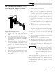

Hot water pip ing must be supported by suitable hangers or
floor stands, NOT by the boiler. Copper pipe systems will be
subject to considerable expansion and con trac tion. Rigid pipe
hangers could allow the pipe to slide in the hanger resulting in
noise transmitted into the system. Padding is recommended
on rigid hangers installed with a copper system. The boiler
pressure relief valve must be piped to a suitable floor drain.
See the relief valve section on page 23 of this manual.
CAUTION
A leak in a boiler system will cause the
system to intake fresh water constantly,
which will cause the tubes to accumulate
a lime/scale build up. This will cause a
NON-WARRANTABLE FAILURE.
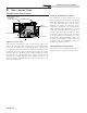
Water Connections
Heating Boilers with inputs of 45,000 - 260,000 Btu/hr have
1 1/2" NPT inlet and outlet connections.
CAUTION
Field installed reducing bushings may
de crease flow re sult ing in boiler noise or
flashing to steam.
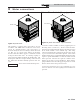
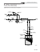
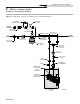
Circulator Pump Requirements
This is a low mass, high efficiency hot water boil er which
must have adequate flow for quiet, efficient op er a tion.
The boiler circulating pump must be field supplied. The
boiler circulator pump must operate con tin u ous ly while the
boiler is firing. Pump selection is critical to achieve proper
op er a tion. A pump should be selected to achieve proper system
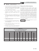
design water temperature rise. A heat ex chang er pressure
drop chart (Table 4C) is provided to assist in proper pump
selection. Also provided is a System Temperature Rise Chart
(Table 4B on page 25). This table provides GPM and boiler
head-loss at various temperature rises for each boiler based on
Btu/hr input. Temperature rise is the difference in boiler inlet
temperature and boiler outlet temperature while the boiler is
firing.
Example: The boiler inlet tem per a ture is 160°F and the boiler
outlet temperature is 180°F, this means that there is a 20°F
tem per a ture rise across the boiler.
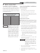
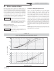
TABLE - 4C
HEAT EXCHANGER PRESSURE DROP CHART
Head Loss, FT/HD
Flow Rate, GPM
CB135
CB180
CB260
0.0
1.0
2.0
3.0
4.0
5.0
0 5 10 15 20 25 30
CB045
CB075
CB090
CB215
0.0
0.5
1.0
1.5
0 5 10 15 20
4 Water connections
26
Installation & Service Manual