
Install Instructions


62
8 Maintenance
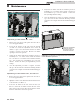
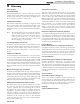
AIR PRESSURE SWITCH
Figure 8-2_Air pressure switch
Adjustment procedure Models 497 - 1257:
1. Remove the upper front jacket panels from the unit to
access the upper chamber.
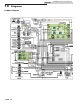
2. Locate the air shutter on the side of the fan housing
(see FIG. 8-3). Turn the adjustment screw on the air
shutter to open or close the shutter. Increase air shutter
opening to increase air pressure. Decrease air shutter
opening to decrease air pressure.
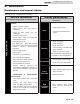
3. Adjust the air shutter until the air chamber pressure is
nominally 1.25 - 1.30 inches water column for Models
497 - 747 and 1.35 - 1.45 inches water column for Models
987 - 1257. See FIG. 8-4 on installations up to 2000 feet
altitude. Contact the factory for high altitude pressure
settings.
4. Once the adjustment procedure is complete, reconnect
the cap to the tee in the hose and check all tubing and wire
connections for a snug fit. Test fire the unit. Reinstall upper
panels.
Adjustment procedure: Models 1437, 1797 and 2067
1. Remove the upper front jacket panels from the unit to
access the upper chamber.
2. Slightly loosen the screws that attach the fan transition box
to the metal base (see FIG. 8-5).
3. Locate the air shutter at the rear of the fan duct (see
FIG. 8-6). Move the air shutter towards the rear of the
unit to increase air pressure. Move the air shutter towards
the front of the unit to decrease air pressure.
4. Adjust the air shutter until the air chamber pressure is
nominally 1.35 - 1.45 inches water column. See FIG. 8-4
for installations up to 2000 feet altitude. Contact the
factory for high altitude settings.
5. Once the adjustment procedure is complete, reattach the
cap to the tee in the hose and check all tubing and wire
connections for a snug fit. Test fire the unit. Reinstall upper
panels.
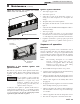
TURN THE ADJUSTMENT
SCREW ON THE AIR
SHUTTER TO OPEN OR
CLOSE THE SHUTTER
Figure 8-3_Adjusting air shutter
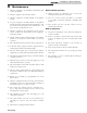
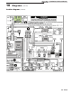
Figure 8-4_Combustion air adjustment with manometer
to set differential pressures
Installation & Service Manual